Eng-Tips is the largest engineering community on the Internet

Intelligent Work Forums for Engineering Professionals

  • Congratulations waross on being selected by the Tek-Tips community for having the most helpful posts in the forums last week. Way to Go!

LTB of beams that just sit on supports 2

Status
Not open for further replies.

Settingsun

Structural
Aug 25, 2013
1,513
0
0
AU
I was at a construction site on other business and noticed ‘stacked’ beams used for temporary works. Working from floor level upwards, there were: a pair of I-beams at 5~6m centres (depth:width is about 2.5 for this size of beam); then a square hollow section on top of the I-beams (ie spanning between the I-beams, loading them at midspan); then a temporary post at midspan of the hollow section. If you looked in plan, the system would be the shape of the letter H. No bolts or welds that I could see, everything was just sitting on everything else.

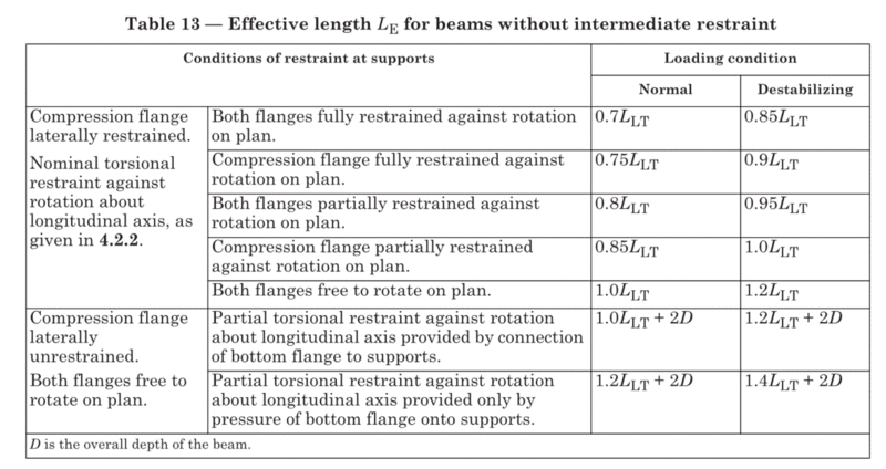
Putting aside rigid-body stability, I’m interested in the lateral-torsional buckling capacity of the I-beams. I found an old topic on this forum with a pointer to British Standard BS5950 which gives about a 20% increase in effective length compared with a beam where the bottom flange is bolted down. See the bottom two rows in the table.

5950T13_heonwb.gif


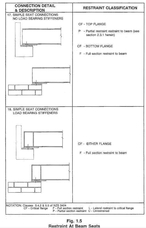
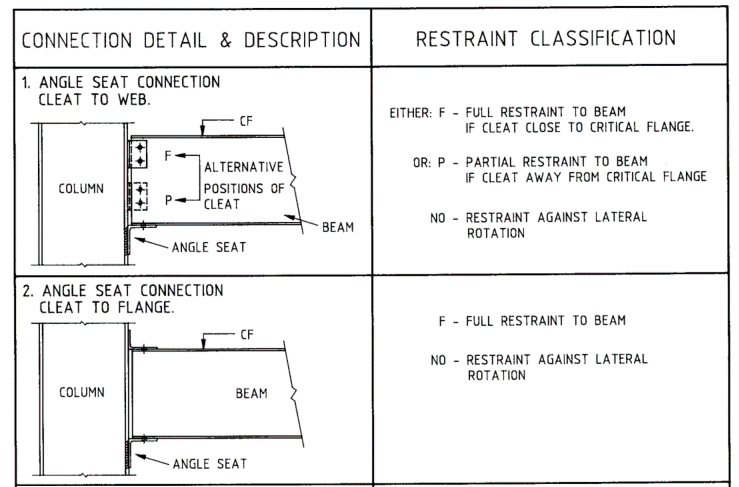
I also have a guideline from the Australian Steel Institute’s journal which gives no penalty compared with having the bottom flange bolted down. See the image below. For comparison to BS5950, partial restraint with top flange loading (destabilising) in Australia gives an effective length of around 1.1*1.4*L, which is pretty close to the 1.4L + 2D from the British code, while ‘normal’ load would give 1.1*1.0*L. The 1.1 factor varies slightly depending on geometry in both cases but is usually 1.0-1.2.

ASIA5_hpx3sn.gif


I’m interested in other references, rules of thumb, gut feels etc. Zero to 20% penalty seems a little low to me.
 
Replies continue below

Recommended for you

PS: The British Standard explicitly covers the case from the big LTB topic last year, namely beams with reverse curvature but with lateral restraints to one flange only. Should I reopen that topic?


5950_reverse_curvature_dvuzvm.gif
 
I am either misunderstanding or you are misreading the Aussie advice, isn't it saying there is no restraint when there are no bolts? You imply no difference or the same??
 
It violate US construction rule, that requires minimum 2 bolts at connections of temporary support member. Also, there is a vertical post at midspan of the HSS beam, wouldn't it has negative moment? What is the question, and what you want to address?
 
Agent666, I believe that the 'no restraint against lateral rotation' refers to the k_r factor.

Edit: Don't you have the NZ version of this document? Would you be able to check?
 
Ok now I understand where you are coming from, all I can say is you are mistaken in your interpretation here.

The tables you presented are primarily about classifying the restraint, U/L/P/F, etc. They have nothing to do with achieving minor axis rotational restraint, on which the k_r factor is dependent and associated with.

k_r is based on achieving minor axis rotational restraint, this is associated with resisting warping of the cross section. none of those details achieve that. Top flange for example has no rotational restraint, those details are free to warp at the location of the restraint.

The New Zealandised version of those tables went as far as removing that unconnected condition, as it provides no restraint at all so it's effectively a U restraint, and you cannot have a UU segment. Now if you connected some of the other beams going the other way in a way that developed some restraint, then you could consider these end regions as FU or PU segments, an upside down cantilever if you like with the support reaction like an unrestrained load at the end of a cantilever acting upwards.

Capture_mgexez.png
 
lateral rotation = twist along the axis of the beam, as opposed to minor axis rotation which is rotation in plan at the point of restraint.
 
I don't think I am mistaken in the interpretation. See other examples below. It can't be both F & U at the same time (detail 2); and detail 1 shows how the document handles cases where the restraint classification is different. There is no such differentiation in details 17 & 18 from the original post.

Note that all 34 details given in the document are classed as no lateral rotation restraint so it was a redundant note which explains removal from the NZ document. What is the title of that document BTW?


ASI_no_lat_rotation_restraint_zz6jxs.gif


4100-5423_yrtgaa.gif
 
Yeah I see now, it wasn't a top note refers to top picture, bottom note refers to bottom picture thing as I interpreted it because the bottom detail without holding down bolts offers no restraint against rotation. Agree now with the fact that the intent is it is implying/relating the rotation to the k_r restraint.

My point remains regarding having no bolts stopping the rotation means no restraint in terms of the definition of F (or P) restraint in the standard, the fact that the bolts were missing in the picture is I believe an error given they were added subsequently and no material change to the definition of the restraint was made. Like some of the other pictures it is probably just saying connected to concrete or masonry achieves the same thing. With no bolts it is classified as a 'U' restraint in terms of the standard.

These pictures are present in two documents here in NZ, the first being the Hera R4-80 - Limit State Design Guides - Volume 1 in chapter 5.
This is shown below and still had the rotation text in the table.
Capture_uykcf1.png


The screenshot I posted earlier was from Hera R4-92 - Restraint Classifications for Beam Member Moment Capacity Determination to NZS3404-1997 which is the most up to date version. There was some text before the tables stating they were updated moving from the 1992 to 1997 version of the standard.
 
Thanks Agent. I see now that the concrete/brick distinction was probably the point. BS 5950 though is clear abouts its intent.

I was hoping your doc was a BRANZ freebie but alas not.

Still happy to hear other viewpoints.
 
Yeah, it is sad in the US that all major code writing institutes treat code like money making property, as well as membership fees.
 
retired13 said:
Yeah, it is sad in the US that all major code writing institutes treat code like money making property, as well as membership fees.

I'm actually in two minds about that. Someone has to pay the costs associated with preparation, publication and distribution of these documents, and it doesn't seem unreasonable to me that the end-user should pay directly, rather than hiding the costs.

On the other hand when documents are available at no direct cost it's certainly something I'm happy to make use of.


Doug Jenkins
Interactive Design Services
 
Hi IDS,
I did have NZS 3404 Part 1 already, which seems to be all that is available on the website unless I've missed something. The link says Part 2 is included but it doesn't come when I download it. Did you get Part 2 somehow?

I understand that the NZ government bought a licence for some main structural standards but not all, and made them freely available. I also like their not-so-random approach to numbering their standards. 31xx are concrete, 34xx for steel, 36xx for timber.
 
The reason they are free/sponsored is that it was a recommendation of the royal commission that access to latest standards for design was seen as too cost prohibitive to designers. Prior to this people tended to use that old out of date copy they had and avoided using the latest versions because they were hundreds of dollars if you bought them one by one, or unnecessarily expensive if you had to maintain a subscription access. So basically they wanted to remove any excuses for not designing to the latest revisions/versions. Still see people doing this of course, but a lot less than I used too!

I'd email them because not including the commentary is clearly a mistake, for example concrete standard has part 2 included. Typically when you download it through a subscription it comes as one file with both parts for example.
 
My frustration is what the major changes in every 3 to 6 years? Even the interim updates, they charge for the full cost. Also, I don't think they are taxed as money making business like publishing houses.
 
Our standards really don't change that often (unfortunately),

For example our timber design standard is 27 years old.... To be replaced soon for the last 15 years... Draft for replacement came out a few years ago.

Etc...

I wish they updated them as often as say ACI or AISC.
 
steveh49 - sorry, no, it's just Part 1.

retired13 - The reason they are not taxed as money making businesses is that they are not money making businesses. Their purpose is to provide a service to their members, which is what they do. Any profit they make stays within the organisation and is used to cover the costs of the services they provide, plus back-up capital for times when income is reduced (like now).

I don't have a problem with that at all.

Doug Jenkins
Interactive Design Services
 
Builders like to do this, and for wide beams I think it’s perfectly ok. It’s how they stack sleepers etc for crane outriggers.

The problem is when it’s your design responsibly it gets a bit more of an issue. If there’s an accident you just know someone will have you over the fact it wasn’t bolted even if it’s incidental to the accident.

We just did one recently. A UC beam supporting props. Builder wanted to just rest it, but we insisted on anchors. They thought we were idiots, because “how can a square roll?”. If doing it at my house I’d take their approach...
 
Status
Not open for further replies.
Back
Top