Continue to Site

Eng-Tips is the largest engineering community on the Internet

Intelligent Work Forums for Engineering Professionals

  • Congratulations KootK on being selected by the Eng-Tips community for having the most helpful posts in the forums last week. Way to Go!

LTB of beams that just sit on supports 2

Status
Not open for further replies.

Settingsun

Structural
Aug 25, 2013
1,513
I was at a construction site on other business and noticed ‘stacked’ beams used for temporary works. Working from floor level upwards, there were: a pair of I-beams at 5~6m centres (depth:width is about 2.5 for this size of beam); then a square hollow section on top of the I-beams (ie spanning between the I-beams, loading them at midspan); then a temporary post at midspan of the hollow section. If you looked in plan, the system would be the shape of the letter H. No bolts or welds that I could see, everything was just sitting on everything else.

Putting aside rigid-body stability, I’m interested in the lateral-torsional buckling capacity of the I-beams. I found an old topic on this forum with a pointer to British Standard BS5950 which gives about a 20% increase in effective length compared with a beam where the bottom flange is bolted down. See the bottom two rows in the table.
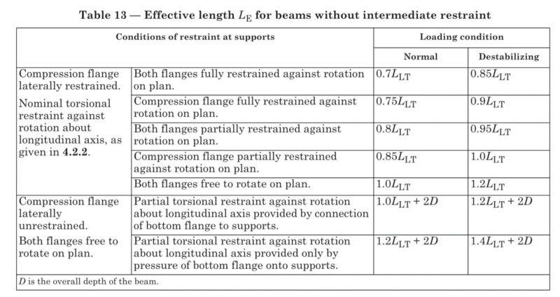
5950T13_heonwb.gif


I also have a guideline from the Australian Steel Institute’s journal which gives no penalty compared with having the bottom flange bolted down. See the image below. For comparison to BS5950, partial restraint with top flange loading (destabilising) in Australia gives an effective length of around 1.1*1.4*L, which is pretty close to the 1.4L + 2D from the British code, while ‘normal’ load would give 1.1*1.0*L. The 1.1 factor varies slightly depending on geometry in both cases but is usually 1.0-1.2.
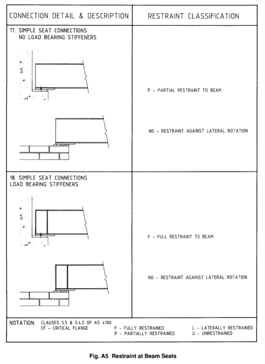
ASIA5_hpx3sn.gif


I’m interested in other references, rules of thumb, gut feels etc. Zero to 20% penalty seems a little low to me.
 
Replies continue below

Recommended for you

I've seen this stacking not work out once about 15 years ago. A suspension bridge with box girder temporarily supported on three layers of criss crossed UC's with no connection between the members. Mid pour of deck one side at one end fell over sideways as the beams swayed sideways. Webs ultimately buckled. People literally running for their life at the time as nobody knew what was going on as the deck dropped down 150-200mm almost instantly.
 
To be fair, they were probably overloaded though to some degree based on how they failed. Ironically the last single top UC in the stack didn't have any stiffeners and was obviously carrying all of the load which contributed more than the fact that it wasn't bolted down. All the stack below this had stiffeners. Contractor designed.
 
AISC Manual of Steel Construction 6[sup]th[/sup] through 9[sup]th[/sup] Edition have provisions for calculating allowable bending stress in beams with unlimited unbraced lengths. One of the equations is valid for any grade of steel. The two-page section from the 6[sup]th[/sup] Edition is attached.

The calcs work, I've used them a couple of times for lightly loaded, very wide flange 10 and 12 inch beams up to 60 feet long with the entire beam being unbraced.

[idea]
 
SRE, is your attachment for the typical case of LTB assessment, with restrained sections at supports and potentially also within the span? It says the unbraced length is usually less than the total span, and imposes a lower limit of 11ksi allowable stress (46% of allowable section capacity).
 
steveh49,

See this thread, Link for new versions of the equation SRE addressed.
 
Steveh49 - The section that I attached yesterday addresses both charts used to select a beam and the equations that are used for unbraced lengths that exceed the values in the charts. The note about 11 ksi allowable stress is one of two cut-off limits where the charts stop. The other limit on the charts is unbraced length exceeding 25 feet.

SixthEd-800_l9zjzv.png


The equations are for conditions that go beyond "normal design" when any of the following apply:
1) Unbraced length > 25'
2) Allowable stress is < 11 ksi
3) Beams not included in the charts.

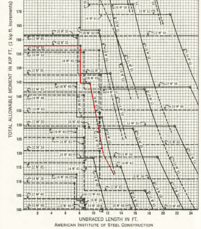
Here is an image of a chart, I've highlighted the line for a 18WF45. A more readable copy of this page is attached.

Chart-400_iifqwq.png


For either the charts or the equations the unbraced length can be all or part of the span:

Unbraced_Length-800_v4cij2.png


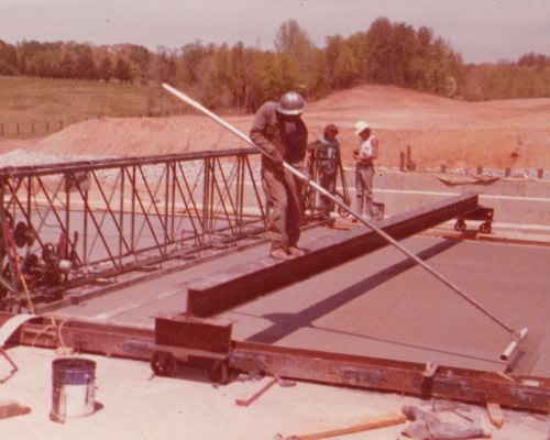
I don't see that the support restraints are addressed. The times I used the equations, the bottom flange was welded to moveable support. The top flange was not restrained in any way at any location. This is a photo of my first work bridge over a fresh concrete bridge slab. Although it does not look like it in the photo, the HP12x53 beam is 35' long.

WorkBridge-500_s2qalc.jpg


The longest work bridge I design/constructed/used was identical to the photo but the beam was a 60' long, HP10x42.
Applied bending stress (beam self-weigh + 300 lb allowance for a worker at midspan) = 6.47 KSI
Allowable bending stress from Equation (5) = 7.22 KSI

I walked across it, stable, but somewhat like a trampoline with a little LTB "wobble" from side to side. Not a problem.

[idea]
 
I always require rotational restraint even for temporary works. I find a way
 
Hi SRE,
In your photo, we'd call the top flange 'partially restrained' at each end according to the Aus code so this case is covered. The restraint of the bottom flange and stiffness of the section give enough to work with. We'd also apply a factor for top flange loading.

I'm talking about the case if you didn't weld the bottom flange. Would you use the same equations for that?
 
Steve - Bottom flange not welded... since the AISC manuals (6[sup]th[/sup] through 9[sup]th[/sup]) don't address the supports, yes, I would use the equations, but with self-imposed restrictions:

1) Only for on-site temporary storage of beams where the only load is the (static) self-weight of the beam.

2) Maximum beam length of 60', all unbraced (if the equations verify this is ok).

3) Brace beams that are "tall" and/or have "narrow" flanges to resist wind load.

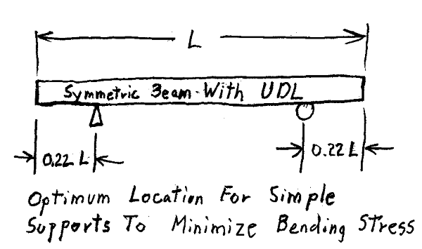
4) Located supports (dunnage) to minimize beam's bending stress. Placing the supports as shown reduces bending stress to about 20% of it's value compared with supports at the ends of the beams. Since negative moment at supports approximately equals the positive moment at mid-span, the beam has to be symmetric.

Optimum-600-1_v6wqwd.png


[idea]
 
Status
Not open for further replies.

Part and Inventory Search

Sponsor