Eng-Tips is the largest engineering community on the Internet

Intelligent Work Forums for Engineering Professionals

Lug Support Design 1

Status
Not open for further replies.

TylerM

Mechanical
Feb 16, 2017
32
0
0
US
Hello Everyone,

I'm trying to calculate the maximum weight each lug on a pressure vessel can support and I'm a little confused about a variable in the equation I'm using. The equation is from the Pressure Vessel Handbook 10th ed.

The variable for H (Lever arm of load) is slightly confusing for me. My question is where is it measured from? (If the pressure vessel is/isn't stiffened with a wear plate)
Lug_support_wbr1ix.png


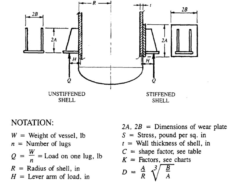
I know that H extends from Q (The location of the bolt hole/Location of load) but I don't know where it ends. In the picture it looks like it extends into the middle of the shell thickness. I've also seen other lug support calculations where it only extends to the outside of the shell. Could you guys place help me clarify where the dimention for H starts and stops?

Thank you for your help,
Tyler
 
Replies continue below

Recommended for you

I have previously interpreted that dimension as the center of a line which connects the most extreme edges of where the lug attaches to the shell. This line may or may not pass through the shell, depending on the shell diameter and thickness.

Remember that the shell is round, so the distance between the plane which the mounting hole (or holes) lives in is not the same distance from the shell everywhere. The method above gives a conservative value.
 
In the figure, it looks like it's the middle surface of the plate.
I think in the anchor chair design, it's taken as the outside of the plate.
Taking it as the middle surface makes sense to me, as a lot of the derivations for plate bending assume a "thin" plate, ie, zero thickness, so there's not a distinction made between a load applied at the inside surface or the outside surface.
 
Looks like shell mean radius (probably corroded) for both sketches to me.

Regards,

Mike

The problem with sloppy work is that the supply FAR EXCEEDS the demand
 
It depends on whether you want to calculate the stress in the shell - the stresses in the weld or in the case of a stiffened case the stresses in the welds of the attachment to the wear plate.
 
TylerM:
Understand how the darn thing works, and being able to draw your own correct/accurate/ truly representative FBD’s (free body diagrams) of how it works, is far more important than worrying about a 1 or 2% change in the length of a moment lever arm. You are talking about an ‘H’ of about 6, 8, 10", and then you are also talking about (t/2) being on the range of .125 or .1875" +/-, thus, [8.125/8 = 1.016]. Unless something in the text immediately around the figure you posted said otherwise, I would think that the middle of the shell pl. thk. is a reasonable line to work from. You haven’t shown the equations you are dealing with or enough of the text around the figure, on the subject matter, to know exactly what you are trying to calculate. Then, also realize that you really don’t know all the possible loads on the vessel within 1 or 2%, and you have load factors on the loads, you have reductions on the allowable stresses, etc. etc. Finally, as likely as not, the equations are some sort empirical equations based on years of good experience, but not intended to imply exact max. stress. Use some good engineering judgement, and realize that you rarely see a failure caused by a 1 or 2% error in stresses or moments used, but you see failures regularly caused by misunderstanding of how the detail works, or poor detailing, or poor workmanship, etc. The actual shell pl. thk. and/or loss of thk. comes into play when you are finally calculating the shell stresses due to the support lugs and their reactions on the shell pl. If you want to worry about something other than .125" of lever arm length, consider what happens if one of the support lugs is applied .125" high on the vessel shell, and then not properly shimmed on its support pedestal. All of a sudden ‘Q’ or ‘n’ change radically. Good clean detailing, without reentrant corners or stress raisers, understanding the load paths, and that they be clean and simple, and how concentrated loads are distributed into the shell pl., good clean weld details and welding without defects are far more important than a 1 or 2% change in stress, as best we know that.
 
Clear is in Pressure Vessel Design Handbook, H. BEDNAR, second edit pag 156 fig 5.9 ( or first edit pag 146)

Regards
r6155
 
In any case H is not an accurate measure the moment arm. The bolt holes are not same as the load point unless you are pulling the vessel up. Q would be at the edge of the thing the support is sitting on.

FEA is better tool and results are often much different.
 
Thank you everyone whos posted. I took all of your comments into consideration. I ended up using jgKRI's measurement because its most conservative, but dhengr's comment was also very helpful.

Thank you all once again for your insight.
 
KevinNZ said:
In any case H is not an accurate measure the moment arm. The bolt holes are not same as the load point unless you are pulling the vessel up. Q would be at the edge of the thing the support is sitting on.

This is true, but it's also a pressure vessel application- which means that conservatism rules the day.
 
Lingeshgdvg,

I used the "Pressure vessels handbook 10th Ed. by: Eugene F. Megyesy" and it walks you through a lug support calculation on page 109. The equations used are as follows (with the variables defined in the first picture of this thread):

Longitudinal Stress:
S_1=±QH/(DR^2 t) (C_1 K_1+6 (K_2 R)/(C_2 t)+D/2(1.17+B/A) *R^2/HA)

Circumferential Stress:
S_2=∓QH/(DR^2 t) (C_3 K_3+6 (K_4 R)/(C_4 t))

For longitudinal stress you need to make sure S_1 plus internal pressure stress (PR/2t) is less than the allowable stress of the shell material times your joint efficiency

For circumferential stress you need to make sure S_2 plus your internal pressure stress (PR/2t) is less than the allowable stress of your shell material time 1.5

Regards,
Tyler
 
Status
Not open for further replies.
Back
Top