Continue to Site

Eng-Tips is the largest engineering community on the Internet

Intelligent Work Forums for Engineering Professionals

  • Congratulations KootK on being selected by the Eng-Tips community for having the most helpful posts in the forums last week. Way to Go!

LV 480V Motor Earth theminal Inside terminal box 2

Status
Not open for further replies.

Michael2009

Petroleum
Jun 24, 2010
49
Hi Guys,


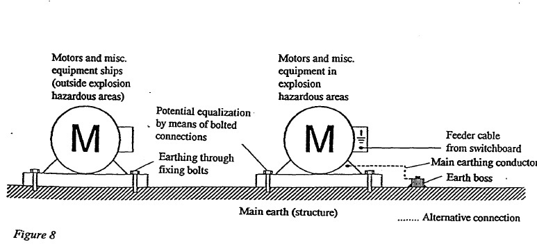
I encounter some of the plant/offshore engineering design for 3phase LV 480V motor earth terminal inside enclosure (terminal box) is connect directly to local ground (Structure). Instead to go back to main switchboard or MCC. Frame earth also to local earth (Structure).

But when I go through some Ex recommendation. for Explosion atmosphere requirement, Motor earth terminal inside terminal box require to earth direct to switchboard or MCC (4 wire for 3 phase, 3C + E). And motor frame is require to earth to direct local ground (Structure)

Which is correct actually?

some even do nothing with the earth terminal inside terminal box...

or all this is subject to earthing system designed?

thanks guys...
Explosive_ATM_motor_earthing_q4azxu.jpg
 
Replies continue below

Recommended for you

The picture on the right is correct assuming you have a modern installation with a grounding conductor along with your phase leads. In older facilities you may find that this is not the case.

old field guy
 
The terminal inside the junction box is for Electrical Code grounding/bonding. The purpose is to provide a low impedance path to ground to ensure rapid detection and clearing of ground faults.
The external ground connection is an API Code requirement to prevent a touch potential from developing between the motor housing and adjacent conducting surfaces and to prevent possible arcing between the motor housing and adjacent conducting surfaces during the short time before the protection devices clear a ground fault.
Both are required.
With only the internal ground connection in use, the path of a ground fault current will be through a phase conductor and back through the grounding conductor in the supply cable. The grounding conductor is usually a smaller cross section than the phase conductors.
In the event of a ground fault in the motor, the phase conductor and the grounding conductor will form a voltage divider from phase to system ground and the voltage to ground at the motor grounding terminal and on the external parts of the motor may rise to over 1/2 of the phase to ground voltage.
This ground connection may not avoid dangerous touch voltages or possible arcing.
The external ground connection may not provide a direct low impedance connection back to the system ground. The external ground connection may not provide a ground path back to the system ground that meets Electrical Code requirements.
Consider a skid mounted pump with the skid set on a dry concrete slab or foundation with an underlying vapor barrier. Consider an equipment skid mounted on anti vibration mounts. The external connection to the adjacent metal parts of the skid may not provide a low impedance path to the system ground.
Use both connections.
The internal connection will provide a low impedance path to ensure rapid clearing of ground faults.
The external connection will provide a low impedance path to nearby conductive surfaces to avoid touch potentials and also avoid possible arcing to adjacent surfaces.
I am not familiar with offshore codes. It may be that your codes recognise the structure as a system ground point and using just an external connection to the structure as a ground point may be safe.
On-shore, using both connections gives good protection in all situations.


Bill
--------------------
"Why not the best?"
Jimmy Carter
 
Both is correct and the photo on the right is to ensure that the equipment is always connected to earth you have less chance of floating earth on your motor.
 
Status
Not open for further replies.

Part and Inventory Search

Sponsor