Continue to Site

Eng-Tips is the largest engineering community on the Internet

Intelligent Work Forums for Engineering Professionals

  • Congratulations KootK on being selected by the Eng-Tips community for having the most helpful posts in the forums last week. Way to Go!

LVL Lateral Support

Status
Not open for further replies.

majbacker

Structural
Jan 8, 2022
10
I am using forteweb to analyze a multi span LVL basement beam. The beam is a drop beam and is pocketed into the foundation walls at each end. The center support is a steel column. Forte has an input for bottom edge lateral bracing. I am assuming there would be no lateral support at the bottom edge of the beam at the center support? In other words, I cannot assume the column provides any lateral support for the bottom edge of the beam?
 
Replies continue below

Recommended for you

This is kind of uncomfortable territory. I think that most folks do consider the column to beam connection to torsionally bracing to the beam so long as the connection constitutes a nominal moment connection of some kind between the column and the roll over behavior of the beam. Things like a deep-ish saddle or a cap plate with some serious screws from the underside are used this way. The whole thing gets a bit sketchy in that this torsional bracing ultimately relies on cross grain bending in the wood member which is usually a no-no for primary load actions.

Any chance this beam is recessed flush into a joist system runs the other way that is deep enough to provide continuous torsional restraint to the beam?
 
I agree.

I am in a bit of a stick situation as the client wants to keep this as a drop beam. I have also recommended a deep saddle type connection but that was a no-go for them too.

It seems like I have two options:

1. Run the beam as only being braced at each end and not the middle. This will require a 3-ply 14" instead of a 3-ply 11 7/8.

2. Require that they add another support to reduce the span which would reduce the maximum moment below the allowable.
 
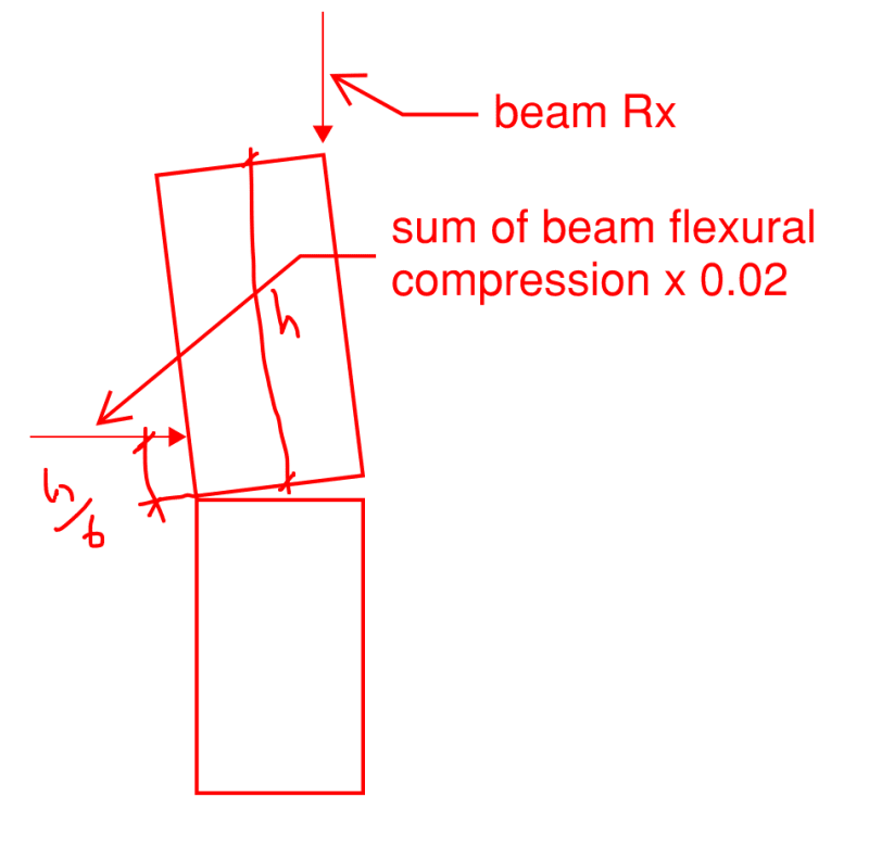
My very strong suspicion is that no connection between beam and post is required for LTB restraint in many cases. I suspect that the gravity load pre-stressing of the joint gets the job done so long as the beam is of sufficient width and has full bearing from below. I've been tinkering with various ways one might prove this analytically but its probably not something that you'd want to hang your hat on considering the source is just some cyber-nutball. I think that there's precedence for this though. I've seen a lot of historic buildings where very stocky looking beams seem to survive on this very principle.
 
Lol well judging from your threads you have plenty of experience and I think that makes sense. It is a 3-ply beam which gives the beam a total width of 5.25". The two spans are approximately 10' and the beam supports two floors. Trib width on first floor is about 13.5 ft and same for second floor. No roof load as trusses span the entire home.
 
Depending on finishes, etc., you could add one of these at each support. I've used them for similar retrofit situations where I felt the beam needed it.
 
Could you run a discrete kicker brace at midspan up into the floor diaphragm above? It messes with the drop beam aesthetic (if I'm understanding that correctly), but less than a midspan column would.
 
With the proportions your are proposing, screws up into the LVL would seem reasonable for bracing. If it was a 3 1/2x18, I might think differently.
 
Thank you all very much for your responses. This has been bugging me for a long time and it is great to have other professional opinions on the matter. Greatly appreciated!
 
This is a very poor man's version of what I eventually hope to do with the pre-stressing model that I proposed. It's predicated upon detailing that would cause the joist members to rise with the beam rotation as shown. In this way, I hope to quantify the question of "how wide is wide enough?".

My feeling on this is that, if this pre-stressing mechanism were overcome. We probably would see distress in a lot of our common post to beam connections. Under beam rotation, both the saddle and screw solutions would tend to create tension perpendicular to grain at the bottoms of the beams.

C01_idumr3.png
 
I've never considered it braced at the column, and just called the unbraced length the length between curvature nodes.
There's also the fact that the beam/column connection also provides positive restraint through lag screws or such, restraining the rotation in KootK's sketch even more. I don't know if I'd seal a design utilizing the concept yet though.
Also, I've never been clear on cross grain bending in LVLs. Surely there's less concern than in sawn lumber. Does anyone know of reference material about it?
 
kissymoose said:
..and just called the unbraced length the length between curvature nodes.

That sounds like inflection point bracing which has been discredited other than flakey stories about using it to balance out conservative assumptions regarding other parameters.
 
The latest edition of Breyer and Cobeen that I own still shows inflection point bracing as being legit.
 
Maybe I'm missing something, but why not just make it two simple spans and eliminate the need for bottom chord bracing altogether? The max moments and deflections will increase somewhat, but maybe your existing design can handle it.
 
The ends of each beam should still be restrained from rotation, so the question of if the column does that still applies.
 
Status
Not open for further replies.

Part and Inventory Search

Sponsor