Eng-Tips is the largest engineering community on the Internet

Intelligent Work Forums for Engineering Professionals

  • Congratulations waross on being selected by the Tek-Tips community for having the most helpful posts in the forums last week. Way to Go!

LVL Splice with Partial Flitch Plates 1

Status
Not open for further replies.

youngblood30

Structural
Jan 28, 2020
14
0
1
US
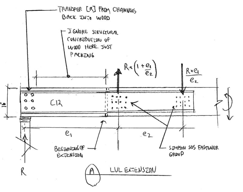
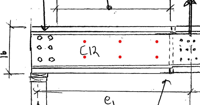
3-Ply 16” LVL currently spans about 20 feet. One support has to be moved 4’ out. They can’t install a new beam for a number of reasons so they proposed a partial flitch plate splice to extend the beam 4’ to the new bearing.

We have about 680plf on this beam which gives me about 6 5/8” bolts at the bearing with 3 bolts 16” o.c. How far past the splice does the plate need to get ran? Going with 2 3/8” plates on each side of LVL.
 
Replies continue below

Recommended for you

You're attempting a moment splice in a wood beam to support sustained loads. That's not a good idea. Even if the numbers work, long term performance is questionable. Find a way to make it stable assuming that connection is a pin - run your "extension" beyond the new post to another bearing point if there's room. Use a steel post with a moment connected, 4' steel beam to pick up the existing (though bracing it back may be tough).

If you can't do those, make the plates run the full length of the beam, or very close to it.
 
1) It's semantics but, given you proportions, I'd call this a partial sistering rather than a moment "splice" per se. Whatever the sistering is, I'd run it out to bearing and have only one moment connection: that between the sistering the main member.

2) Because of #1, I'd be inclined to do this with a pair of 12" channels rather that flat plate. Or maybe just LVL pieces if the numbers worked.

3) To minimize fastener slip induced deflection, I'd want to get the moment connection done with a lot of smaller, distributed fasteners. Simpson SDS or something like that. You'd set it up as two groups of fasteners separated horizontally to provide a lever arm between the two groups. As such, I imagine that you're going back into the existing member 2' to 4'.

4) Many engineers would include some epoxy adhesive between the wood and steel. I normally wouldn't, myself, for an application like this.

5) I suspect that the deal breaker here will simply be the scale of your loads relative to the capacity of a typical screw. I think that you'd wind up needing an unreasonable quantity of screws that would take up too much space considering edge distances and fastener spacings etc.
 
I sharpened the pencil a bit. The load distribution on this beam is uniform to about mid-span then it goes trapezoidal (there is an interior bearing wall we will be using that reduces the trib area on this beam)down to zero at the end with the splice. I ran the 3-ply LVL with the full span(assuming no slice) and it passes. So my thinking is now to just deal with the shears and moments at the splice location and design the fasteners to transfer this load into the steel. Furthermore the bolts at the new bearing will also need to be designed for the shear from the full beam but how far beyond the splice does the steel need to run....
 
youngblood30 said:
...but how far beyond the splice does the steel need to run....

KootK said:
You'd set it up as two groups of fasteners separated horizontally to provide a lever arm between the two groups. As such, I imagine that you're going back into the existing member 2' to 4'.

The only way to answer that question definitively is to run the numbers.
 
The plates work fine but I am struggling with the bolt spacings and pattern at the splice. I believe the NDS allows to multiply the least lateral value by the number of shear planes in the connection. (1880lbs) I have about 5k of shear and 10.5k-ft of moment to resist at the splice. Trying to get a 3x3 grid on each side of splice to work but its tight....any suggestions? (besides scrapping this whole idea lol)
 
I really think you need to go read KootK's post a little closer. He essentially told you what you should be doing. Now you just need to figure out if it's doable given fastener spacings and edge distances. The nice part about the smaller diameter SDS screws, is you can put significantly more fasteners in the same space compared to thru-bolts.
 
I understand slippage is the main concern after the numbers check out but going with the smaller 1/4" SDS gives me about a 12x12 grid on each side of the splice....just seems like a lot of holes. Im Taking the moment and dividing by the height of the group to get the forces on the fasteners furthest away from the centroid.
 
It will be quite sloppy otherwise. Trust us when we say this.

The other nice part about the SDS screws, no drilling of the wood required. They can punch all the holes in the steel at the shop and then a guy with a screw gun just drives screws on site.

With bolts, they punch bolt holes in steel in the shop. Then they lift the beam into place, mark locations, attempt to drill perfectly horizontally (note: unlikely to occur), put piece back up, slide bolts through, find out they don't line up on the back side, ream some of the holes out larger, etc. It's a damn nightmare.
 
Probably best to have the bearing transfer done with screws too. And/or move the channel flanges down to bearing.

c01_xygqmf.jpg
 
KootK....thanks for the sketch! no need for screws on other side of splice? I see you are just saying it’s a filler on that side but I would image it would help with transferring the moment at either side of the splice. No?

I agree with the screws especially for ease of construction....contractor just had his heart set on a bunch of bolts. Hoisting 200lb of steel while trying to get everything lined up sounds like a doozie....
 
If you take a close look at the stiffness of the contributing elements, the "new wood" isn't going to contribute in any meaningful way - screws or no. I'd still put screws in it, but that's more to stabilize the channels and keep the wood from falling out of the assembly.
 
youngblood30 said:
...no need for screws on other side of splice? I see you are just saying it’s a filler on that side but I would image it would help with transferring the moment at either side of the splice. No?

I would probably do something like I've shown below with the red fasteners. That, for similar reasons to what phamENG mentioned. Stabilize the channels, tie everything together, etc... I would not, however, count on the red fasteners for any significant structural function. I intentionally left these fasteners out of my original sketch to highlight the difference between my proposed load path and what I think your proposed load path is. This is how our respective load paths appear to me:

You: moment in existing wood --> moment in steel --> moment in new wood.

Me: moment in existing wood --> moment in steel.

The more times that you try to transfer the moment through the wood, the greater your potential for undesirable fastener slip. So I feel that it's best to do that only once.

c01_ifa7s3.jpg
 
Just following along here, and am wondering if a bottom flange splice plate would be beneficial in addition to channels/flitch-plates? It seems to me that would provide good stiffness and prevent excessive long-term slip in the connection?
 
Coming up with 7x7 grid at 2" o.c. for 1/4 sds screws(380lbs each)....calculated all shear forces in each screw from combined moments and shears about centroid of the fastener group...we have 2 sides and essentially each side should see half of the calculated load from each screw, correct? If so, how deep do the SDS screws need to penetrate the existing LVL to make sure full transfer of load into both channels/plates? A 2.5 long SDS should get me about 0.5" into middle LVL ply

I know on typical broken truss chord splice repairs they use a 4" o.c. spacing with nails that fully penetrate the scab and broken chord. Then they stagger the nails on each side of splice to get a net 2" o.c. spacing....I know this is more of a tension/compression splice but it is still the better option with a moment splice?
 
In my opinion, you should be going to 3.5" long ads screws and grabbing at least the full 2 of 3 plus. And I'd be splitting them half on each side, and then rounding up to a nice number.

If you need 49 total, that's 25 per side. I'd probably do 4 columns of 7 screws each side. Set the columns 4" apart, and stagger them 2" on the other side.
 
Status
Not open for further replies.
Back
Top