Continue to Site

Eng-Tips is the largest engineering community on the Internet

Intelligent Work Forums for Engineering Professionals

  • Congratulations KootK on being selected by the Eng-Tips community for having the most helpful posts in the forums last week. Way to Go!

M & N interaction is safe for construction phase? concrete columns 1

Status
Not open for further replies.

Pretty Girl

Structural
Nov 22, 2022
60
I have noticed that the Moment to Axial load interaction diagrams (and or equations) are widely being used to design concrete columns. But I noticed that the principle behind it is just to calculate how much resistive moment (Mc) can be utilised from the axial load and then we are removing that from the main design moment. Although we're reducing the design moment than it actually is, the column is safe as the axial load will act in favour to counter-attack the moment. so it's considered safe. And it will effectively reduce the amount of reinforcement area needed.


example (simplified):

Mrd = Mc + resistance from reinforcement

So, it's considering like 20-30% (or even zero) of the actual moment for design. ( for example If we have the Mrd of 100kNm, then after reduction the Mc, it would be like 50 kNm or even 0 (zero) kNm if the moment resistance provided by axial load (Mc) is big enough to cancel out the actual design moment (Med). But it still will be safe as the axial load will be there to prevent the column from bending.

It may be safe for one or two story buildings.

But I noticed, when you construct the column (in construction phase) for multi story buildings, it's not safe. Imagine you have casted concrete columns for the first floor of the multi story building (say, it has total 20 floors) and you don't have most of the resistive moment from axial load (Mc) yet (because you have not constructed upper floors yet). However, what you will do next is cast the beams or slabs to the columns for that floor, which would apply 100% of the expected moments on the column(s).

However, we never designed that column to have 100% of the moments in the first place, and we expected the axial load to resist the moments. But the problem is the axial load to resist the moment is not there yet. So, this column will definitely fail in the construction phase (after casting the beams and slabs to it). So, why are we using N & M interaction? We can just design the column to the 100% of the moment that it will be encounter. Is it just for the cost savings (to reduce r/f, reduce dimension etc)?

Or is there any valid unavoidable reason that we're taking axial load into account to reduce design moments?
 
Replies continue below

Recommended for you

Pretty Girl said:
So, it's considering like 20-30% (or even zero) of the actual moment for design.

That's not right. The axial load increases the bending capacity of the section up to the balance point, then after that it starts to reduce it.

When you use an interaction diagram you plot the bending capacity against axial load (applied at the centroid of the section), then you plot the design applied bending moments, with the axial load applicable at that stage.

You don't reduce the applied moments, and you don't plot a moment during construction with the axial load in the complete structure.

The whole point of interaction diagrams is that you can plot the bending moment with the corresponding axial load, so you can include every potentially critical load case on the one diagram.

Doug Jenkins
Interactive Design Services
 
@IDS
Thank you for your reply.
I'm not quite sure if I'm referring to the same
For example the following equation can be used to get the resistive moment from given Ned (axial load) and provided reinforcement. So I can see the "Mc" which consists of the Ned (axial load) effectively reduces the amount of reinforcement required to resist the given moment.

Screenshot_2023-08-07_at_12.10.47_am_e3sjia.png


Screenshot_2023-08-07_at_12.14.49_am_k2hvk7.png


And the "Cc" is basically "Ned" when you place reinforcement symmetrically.

So I can see the Ned (design axial load) effectively reduces the reinforcement needed to resist the given moment. Am I wrong?
 
You need to check all possible load conditions in the design of the column, not just the final condition.

One would be the construction case where there is a much smaller Axial force from the beam without axial force from the floors above with the moment from the beam.
 
Pretty Girl said:
And the "Cc" is basically "Ned" when you place reinforcement symmetrically.

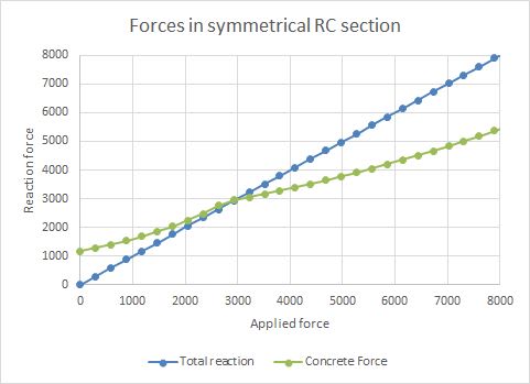
But it isn't; here is a plot of concrete force against total reaction (= total applied axial force):

Concrete_force_gh3wol.jpg


The main points are,

1) The moment due to the concrete compression is part of the total moment resistance of the section, you don't subtract it from the applied force.

2) You have to include the actual applied axial force for whatever load condition you are looking at. Why would you use the axial force from a totally different load condition?

Doug Jenkins
Interactive Design Services
 
rapt said:
You need to check all possible load conditions in the design of the column, not just the final condition.

One would be the construction case where there is a much smaller Axial force from the beam without axial force from the floors above with the moment from the beam.

Thank you for your reply.
I understand you need to check for "moment only and zero axial load" as a load combination to mimic and compensate construction phase loadings.

However, if you're checking the column for the "moment only and zero axial load" as you're saying as a load combination, what's the use of placing the N (Axial load) into the interaction diagram?

Since you're checking it as a load combination, you're always removing the axial load and checking. Checking means designing the column to resist moment without the axial load.

So, what you basically do is "adding axial load into the equation (or with N & M diagram) and removing it again through load cases" and then "designing the column without the axial load at all".

And it's compulsory (which means you have to do it anyways, each and every time). So, each and every time you design you need to remove the axial load (as a load case). Why don't you remove the Axial load (N) from the interaction diagram first anyways and then just design the column for moment and separately for axial load? that would render a more safe column even without checking that construction phase load combination.

What's the actual use of adding axial load and then removing it anyways? you're anyways design the column not to "benefit" from axial load anyways (moment only except the concrete area lambdaX to resist axial load)

As I see there is no clear difference (and or benefit) between the

1. N & M interaction + construction load case with no axial load
2. Just design reinforcement for moment and concrete area for axial load separately

Am I wrong?
 
IDS said:
But it isn't; here is a plot of concrete force against total reaction (= total applied axial force):

Thank you for your reply.
As I see, Cc is just safety factors multiplied by the concrete strength and area that resist the axial load. If you focus on the concrete area, it's just "b x lambdaX". That means that area must resist "Ned" to have a safe column section for axial load.

That means if you mirror the equation, "αcc * η * fcd * b * λx" should be equal to or greater than "Ned".

So if you wanna know how much concrete area will be needed to resist the axial force, you can just use
αcc * η * fcd * b * λx = Ned

That is identical to the Cc below,

Screenshot_2023-08-07_at_12.35.05_pm_m2yr2y.png


That means Cc = Ned

Am I wrong?

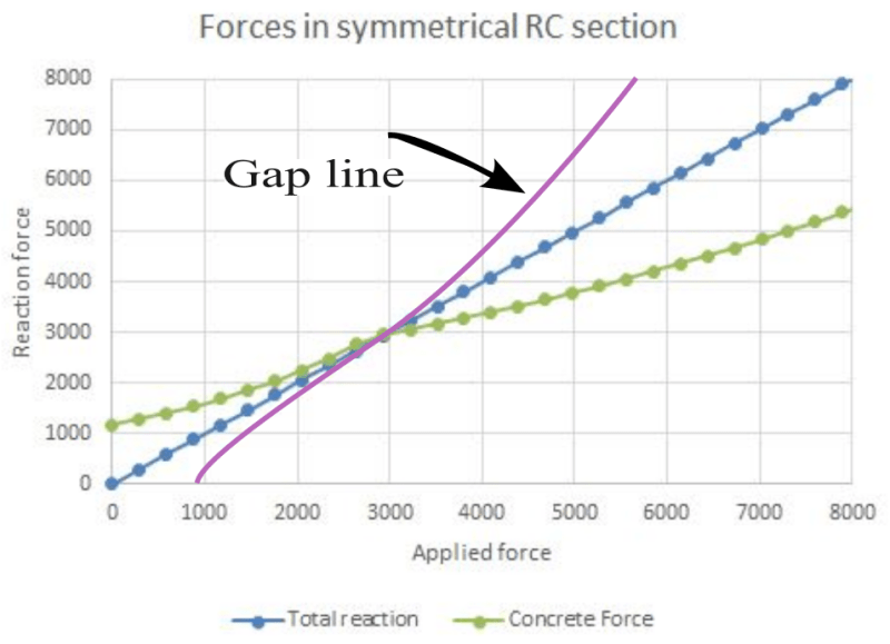
Further, are you sure the equation you used to calculate your chart is correct? I noticed that when your "applied force" is 5000, your "reaction force" from concrete is only 3800, that means your column has failed.

I think something is missing in your chart there's a gap between total resistive force (blue line) and the force provided by concrete (green line). What fills that gap?
To come up with your blue line (the safe column design), you added something (the gap) to the green line data. So what filled that gap in your equation?

If you use above equation that I have referred to, you can just find out how much concrete area you need to resist the axial force and your column will never fail on axial force. And you'll easily end up with your "blue line (total resistance line)" without the "green line (concrete) + your gap(which you didn't show in your chart)"

I added your "gap line"
Screenshot_2023-08-07_at_2.01.20_pm_ubzi4t.png


But without all those concrete resistance + gap (unknown), you can end up with your blue line with the above equation if you substitute Ned as Cc
Am I wrong?
 
Pretty Girl said:
As I see, Cc is just safety factors multiplied by the concrete strength and area that resist the axial load. If you focus on the concrete area, it's just "b x lambdaX". That means that area must resist "Ned" to have a safe column section for axial load.
...
That means Cc = Ned
Am I wrong?

Yes you are wrong. You are ignoring the force in the reinforcement. The sum of the forces in the concrete and the reinforcement is equal to the applied force. In the example in the graph the nett force in the reinforcement is tensile up to about 3000 kN applied load, and after that it is increasingly compressive. At 5000 kN applied load the forces are
Concrete: 3659 kN
Top steel 2306 kN
Bottom steel -965 kN (tension)
Total 5000 kN compression


Doug Jenkins
Interactive Design Services
 
Status
Not open for further replies.

Part and Inventory Search

Sponsor