Eng-Tips is the largest engineering community on the Internet

Intelligent Work Forums for Engineering Professionals

Magnetic Arrangement Selection 2

Status
Not open for further replies.

ZachTheEngineer

Mechanical
Jan 25, 2024
6
0
0
US
Hello everyone this is my first post!

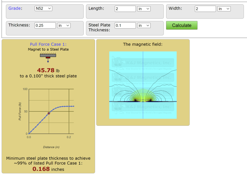
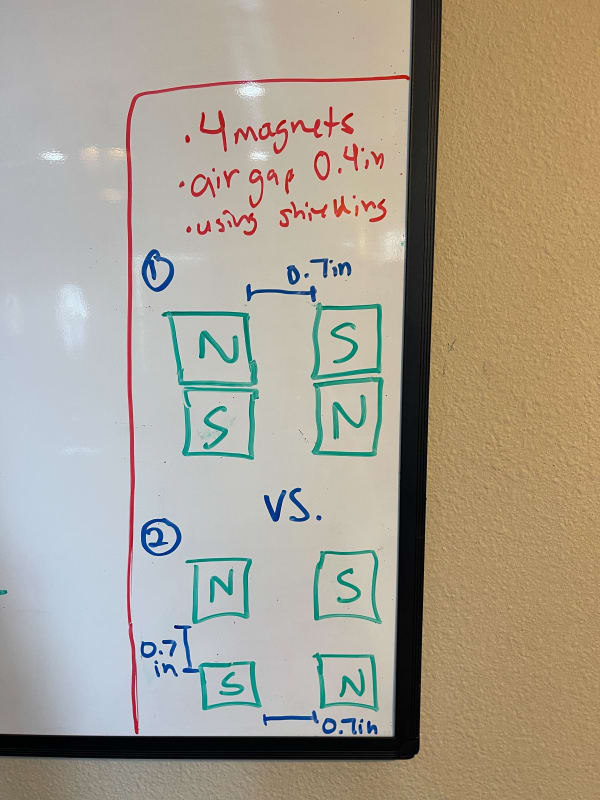
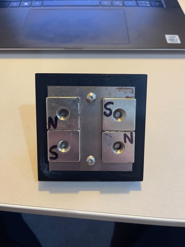
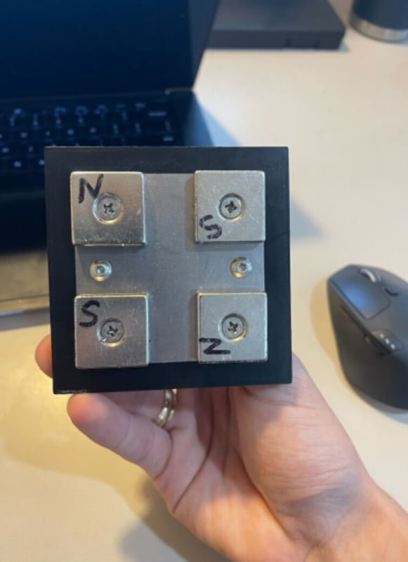
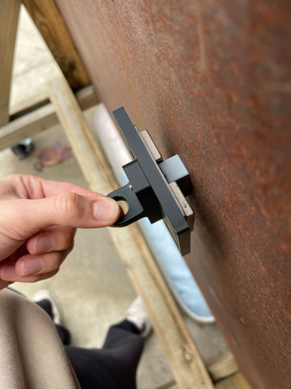
High-level question about magnet arrangements and which might create a stronger adhesion force. I am using an alternating polarity arrangement because I have tested that to be the strongest. The air gap (ground clearance) between the magnet faces and the thick steel wall is 0.4 inches. Also, there is a 0.1-inch thick steel shielding plate that also acts as a yoke. Mathematically, will arrangement 1 or 2 generate the strongest adhesion force at this ground clearance? Thanks for any input!

IMG_9821_pgairz.jpg
IMG_9826_e8x6t6.jpg
IMG_9827_mkcxhk.jpg
IMG_9824_sourbg.jpg
 
Replies continue below

Recommended for you

Are you sure that your backing plate is not saturated?
I would go a lot thicker.
I favor 2 because of your standoff distance.
It reduces shunting of field directly between the magnets.

= = = = = = = = = = = = = = = = = = = =
P.E. Metallurgy, consulting work welcomed
 
Thanks for a swift reply @EdStainless!

As far as saturation goes on the shielding plate, I think you are right. The weight of the assembly is a constraint for the project, the low as possible assembly weight with the strongest force from 4 magnets. Of course, the curve for the thickness of plate vs adhesion force would eventually flatten out and an optimal thickness would be achieved.

I tried doing experimental tests and the setup #2 seemed to achieve better but I was struggling to get consistent results. That's why I am resorting to a mathematical approach or simulation with Ansys Maxwell.
 
For some context, this assembly will be mounted under a magnetic wall-climbing car. That is why the assembly weight is crucial for me, it will eat away at my available payload. Thanks
 
Take some thin shim stock and see if there any attraction to the back.
In #2 you don't need the center, drill it out and make the plate thicker.

= = = = = = = = = = = = = = = = = = = =
P.E. Metallurgy, consulting work welcomed
 
So saturation doesn't necessarily care about surface area, it's more related to the thickness of back shielding? If that is true then your point about removing mass in the center and thickening is very smart.

For the thickness of the backplate is there a calculation or anything to find the optimal thickness to do? K&J calculator has a good thickness setting that mentions the optimized thickness. The magnets I use are 1 x 1 x 0.25 inch. So there are 4 of them that's why I assumed a 2 x 2 x 0.25-inch magnet. See the picture. It suggests a 0.168-inch thick plate, but the way my magnets are spread out and alternating polarity has to make this more complex.

K_J_Thickness_Calc_yhph2y.png
 
What is the Br of your magnets? I seem to recall something just over 13kG.
The back plate should be able to handle the full flux.
If you backing is plain steel it should handle about 18kG min.
But your picture doesn't match your description.
You used a 2.7" sq plate didn't you?
I might try 2.5" sq, hole in the middle, and 3/16" thick plate of mild steel (1010 or lower C).

= = = = = = = = = = = = = = = = = = = =
P.E. Metallurgy, consulting work welcomed
 
Thanks for the insight.

The Br is 14.4 on the magnet website. The dimensions in the steel plate thickness calculator are for the magnet dimensions, not the steel plate. Since I have 4 magnets (1x1x0.25 each) I combined them to be 1 magnet with dimensions of 2x2x0.25in. I combined them all because the calculator can only do 1 magnet input.

I did use a 2.7" square shielding though. Do you think I should reduce it to 2.5" which will, in turn, bring the magnets closer together? Thanks
 
Teh size of the backing only really matters related to the mechanics of your system.
2.5" sq should still work the same.
The thing about thickness is that if it can't carry the full flux then you are losing holding power.
Your magnets flux comes from a 1 x 1 area.
I would have started at 0.75" and then thinned it until I saw a drop in strength.
If you are milling steel off of the back and the chips are sticking to the back then you are too thin.

= = = = = = = = = = = = = = = = = = = =
P.E. Metallurgy, consulting work welcomed
 
Have you even tried Halbach Array arrangement w/o pole pieces?

for your current design, hte reason No2 gives you stronger force is probably because it is symmetric, in No 1 some filed could be cancelled out.
why did you pick up a distance of 0.7'' between magnets? make it 0.5'' or closer to see if you can get a higher field.

it seemed you misunderstood K&J calculator. the calculated plate thickness refers to the steel for your magnets to adhere. The pole piece (for shielding and conducting) is always the thicker the better until to the point any increase in thickness cannot lead to a higher force.

The magnetic flux won't go through the central portion of your pole piece, and so it is literally useless, you can cut off to save some weight.
 
Thanks, MagBen,

I have tried the Halbach array it was fun to learn about and prototype but I found for machining, assembly, and holding the magnets these flat ones with countersink were best. The Halbach array was great though.

The 0.7" was selected using Ansys Maxwell about a year ago when I had access to it. At the current air gap of 0.4", I put the magnets in the simulation and moved them farther from each other until the maximum adhesion force was found. That happened to be around this 0.7" number. I tested some with 3D printing holders and found the force increasing the farther they were apart. I never tested with 0.7" though, that's going to happen soon.

That is a great insight into the way the flux travels only through the backside of the magnet on the pole piece. I will shave weight on the next waterjet piece.

Do you think the 0.7" gap was possibly wrong on my ANSYS testing? I was no expert with that software and sort of played around until I got results. Thanks for the reply!
 
I donot use FEA simulation for years, and have no access anymore. I feel you could decrease distance with a higher force, but not sure. you may do a trial and error.

When you did simulation, did you add the pole piece? the pole pcs can make a big difference. longer distance will increase reluctance but decrease repelling effect (flux cancellation). The pole piece changes fundamentally the flux path. since the cross section area of the pole piece (0.1x1) is much smaller than the magnet (3.14 x .5^2), although the Bd is higher in pole piece than in the magnet (assuming 1.8 vs 0.6kg), the pole piece is probably saturated. you may want to increase pole piece to .15 to .2''.

also, your gap is 0.4, relatively large, and the Pc is low. recommend trying two 1x0.5'' magnets, instead of four 1x.25'' magnets, you may get a higher force.
 
Status
Not open for further replies.
Back
Top