Eng-Tips is the largest engineering community on the Internet

Intelligent Work Forums for Engineering Professionals

  • Congratulations waross on being selected by the Tek-Tips community for having the most helpful posts in the forums last week. Way to Go!

Main bearing loads 4

Status
Not open for further replies.

RoarkS

Mechanical
Jul 10, 2009
245
0
0
US
Howdy,

Single throw crank shaft with articulated rods. 5 cylinder radial. I've balanced the crank inertia loads the best I can variable about 871.8 lbs with the CG moving out max .155 inch... I tried it doesn't get better than that. I'm guessing that's kinda rough but it's a big engine. 450in^3

Now what I'm curious about... I have an actual gas pressure plot from a nearly identical cylinder (It's form exactly what you would expect for a 4 stoke SI engine)It's peak pressure is 880psi! That results in a parallel cylinder force of 18,100lbs!!!

If I take the average pressure of that entire actual gas pressure plot for 720° I get 117.25psi.

and finally for fun my estimated IMEP is 214 PSI.

My only design reference that gets into this level of detail for determining bearing loads I could find... completely ignored the Peak pressure force looked to an "Average" force of which I cant derive from the table data how the "average" value was obtained.

Is that peak pressure a shock load that happens so fast the bearing doesn't really "see it"... other? I would like to understand their reasoning to make a sound engineering judgement for bearing selection.

Thanks!
 
Replies continue below

Recommended for you

Questions:
[ol 1]
[li]What kind of bearing you intend to use?[/li]
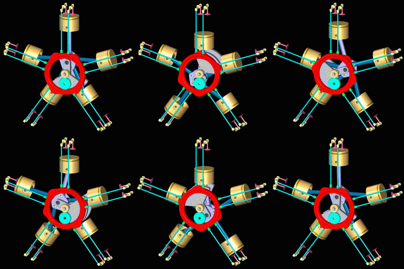
[li]Which bearing in the animation below are you trying to size?[/li]
[li]Do you have a link to the reference that suggested use of average pressure?[/li]
[/ol]
Radial_engine_timing-small_edpjf2.gif


Most large engine use hydrodynamic journal bearings which "float" the shaft on an oil film pulled between the shaft and the bearing wall. EPI gives a nice summary of these bearings. The paper "Journal Bearings Subjected to Dynamic Loads: the Analytical Mobility Method" illustrates how complex the analysis/design/specification of such bearings can be. For what it's worth, I see no mention of averaging shaft loads in the paper's calculations. That being said, it does take time for the oil supporting the shaft to "leak" radially to the lower pressure area on the unloaded circumference of the shaft or axially out the end of the bearing, so perhaps there' a rule of thumb that permits smoothing of the cylinder pressure waveform (it's unlikely to be a simple average, however, and would most certainly include RPM).

Once you answer the questions above, I may be able to provide additional input.

P.S. I don't know how useful it is given there are no five-cylinder radials in the list and old engines didn't likely produce pressures as high as modern engines, but the paper "Crankpin Bearings in High Output Aircraft Piston Engines" provides tables describing the bearings and loads associated with a good number of old radial engines using articulating rods.
 
RodRico

A1. Cylindrical Roller bearing has been traditional used in Jacobs radials. However without "smoothing" of the wave form I can find none that are capable that can fit in the assembly. I initially thought I would end up with a Hydrodynamic bearing, and intend to do so with the "crank pin"... but have been advised against it for the mains largely because of traditional usage of rolling element bearings in radials.

A2. In that animation... I would imagine there is a "main bearing" mounted behind the yellow sun gear in the middle in front of the grey master rod, along with an accompanying bearing on the far side of the master rod. "main bearing" for this Thread to be the bearing which supports the crank assembly to the engine case. These two main bearings support the radial components of the rotating mass inertia, and gas pressure loads. The before mentioned "crank pin" bearing would be the interface between the Grey crank assembly, and purple master rod. For reference: A third axial "thrust" bearing not shown in the animation above deals with propeller thrust... but I'm not to that one yet... besides it's forces are relatively mundane in comparison.

A3. Liston, Joseph. "Aircraft Engine Design" First Edition. McGraw-Hill 1942. Specifically Figure 5-21 describing Front and rear main bearing polar diagrams. Through the book, he designs around a theoretically constructed gas pressure indicator card whose peak force is roughly 4580lb and Ave Force is 1807 lb... much lower than my machine.

Liston has a fairly complete Hydrodynamic bearing design section that I'm pretty familiar with. Just looking for proper method for inputs of their design.

Looking at "JOURNAL BEARINGS SUBJECTED TO DYNAMIC LOADS: THE ANALYTICAL MOBILITY METHOD" I don't see their input gas pressures/inertial forces.

Your last "Crankpin Bearings in High Output Aircraft Piston Engines" Very nice... that will take me some time to digest. Have a look at table 11 and surrounding content. Wow... those pressures are up there. Maybe my problem is assuming that I can find a COTS bearing for the application.

My engine isn't a multi row radial, so the possibility going to hydrodynamic mains exists...In fact I'm pretty interested in the idea just never seen it done in a radial... nor have a I seen places like King bearing produce a full circle bearing for a bore...as the case doesn't split on the bearing bore like it does for typical Horizontally Opposed aircraft engines.
 
No experience with radials but most Honda 4-stroke single cylinder motorcycle engines use fully rolling-element bottom ends. (Mine does.) Perhaps check what they're using for crank bearings relative to cylinder size.

I realize that your situation has more than one cylinder ... but it's only got one cylinder with anywhere near peak cylinder pressure at a time. Every other cylinder in the top-dead-centre order is a firing, i.e. the firings are 144 degrees apart.
 
BrianPetersen Someone mentioned that to me a few weeks back. Would you happen to be able to look in your manual for a bearing part number and willing to share? I could at least see what flavor of bearing is being used. Just FYI I am estimating right now I'm Looking at about 70mm for the bearing inner ring bore because of required drive shaft features.
 
It appears that the crankshaft main bearing for a Honda CBR125 is a 6207 deep groove ball bearing, 35mm ID 72mm OD 17mm width. This is for an engine with 58.0mm bore and 47.2mm stroke, and which makes a romping stomping 12 horsepower.

 
BrianPetersen,

Thanks!

One of the ones on the radar right now is a 6314. I've got 2 other threads asking about how to mount such a thing. Is it a press fit into the housing and onto the crank? Is the case split?
 
There are 2 such bearings on the crankshaft in question, and the crankcase is vertically split. One of them is press-fit onto the crank (in fact, that bearing and the whole pressed-together crankshaft and connecting rod and big-end con-rod bearing are one part number from Honda) and if I remember right, a slide fit in the crankcase (otherwise you would never be able to assemble or disassemble the engine). The other one is press-fit into the case and a slide fit onto the crankshaft but if my memory is right, there is a collar on the crankshaft on the other side of that bearing and a nut on the other side of that (there are some other parts involved - flywheel, starter clutch), which ends up clamping that bearing on the crankshaft, thus locating the crank end-to-end on the bearing that's press-fit in the case and allowing the other one (which is press-fit on the crank but a slide fit in the crankcase) to accommodate thermal expansion. The crankcases are cast aluminium as per standard motorcycle practise.
 
@BrianPetersen That some details there sir. Thank you!

@RodRico... Yeah those and the one from timkin are telling me it's a no go with the max force. As Brian there illustrated there are some issues building it up with a deep groove. I'm actually leaning towards some Timkin Roller bearings.
 
Tapered roller bearings? You'll have to work out a way to set the preload correctly and have it stay correct through the plausible range of thermal expansion. I'm pretty sure there's a reason why Mr Honda designed this engine so that all the end-to-end location is done in one bearing and the other one is free to move at its OD. I'm also pretty sure there's a reason they only do this on small-displacement single-cylinder engines, and use automotive-standard-practice hydrodynamic bearings on all of their high-powered engines. Even if the crank walks end-to-end a little due to thermal expansion, there's enough slop at the small end of the con-rod that it won't matter, and the drive to the clutch is through a straight-cut spur gear, which won't care, either.

Tapered rollers work ok in rear-end differential housings and transmissions and the like, but those operate generally pretty close to uniform temperature - no foreseeable huge thermal stresses - the temperature of a rear axle housing might change as a whole but it doesn't have internal bits and pieces that are significantly different from ambient because of combustion happening inside.
 
@BrianPetersen

I've given serious consideration to two taper roller bearings as the propeller put an axial load on the assembly... but figure I'll stick with one deep groove in the nose of the engine for end to end location... let the other two "float" axially.

I was thinking cylindrical roller bearings (not taper). They come apart just like taper roller bearings so I can assemble the unit easier.
 
I’m using deep grove bearings on the “crank shaft” but I also plan a double row angular contact bearing on the propeller (output) shaft.
 
Cylinder pressure has no effect upon engine balance. The gas force pushes upward with the same force exerted downward and gas force balances out. So whether you're at half throttle or full throttle the balance is the same. See Den Hartog's Vibration book.

Get a hold of "Analysis and Lubrication of Bearings" by Mack and Shaw for good descriptions of radial engine bearings.

Many of the master rod bearings were a floating shell arrangement with an oil film on the O.D. and I.D. There are exceptions, of course.


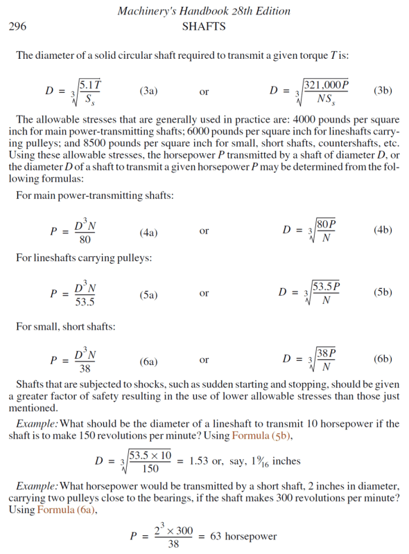
I went into my math model (which defines values for my parametric CAD model among other things) to review how I selected my bearings and found I based the selection on shaft size; I applied a 5x safety factor to the 4000 psi stress limit (800 psi max stress) used to transform equation 3b to equation 4b below. In the cell where I specified the 5x safety factor, I have a note that says "required to force selection of the same bearing as the Honda GX200 engine which produces slightly greater HP and torque." [neutral] Since my six cylinder radial two-stroke engine is far more balanced than the single cylinder GX200, I feel the selected bearing is more than adequate. It's just not a very pretty method. I hang my head in shame. [mad]

Picture1_tg5jeu.png
 
EHudson

Just looked at his Hartog link. I can understand that the gas pressures equal out as far as vibration,That's one thing... but the stress path from the top of the cylinder to the shaft is still through the main bearings. Are you saying the bearings would not "feel" the gas pressure load(s)?

I'm thinking of it like this... If I motored the engine up to it's RPM with an external motor... that would be how I would balance the rotating mass (pistons, wrist pin, con rods, crank) I got that under control. But with actual combustion that force is getting sent into the structure of the cylinder, bolted to the crank case, radially through the main bearings, into the crank shaft.

Trust me... If I'm wrong I would be ecstatic because that's a MUCH smaller (cheaper) bearing. Will look for your Mack and Shaw when I get home.

RodRico I'm all for you method once to get "out" of the engine but inside I would be a little more concerned... difference between a rotor mast support bearing vs the engines main bearings. You mentioned a prop... Water or Air? If Air... what shaft/hub you using for the prop mount?

EDIT: EHudson, I ordered Mack and Shaw.
 
Of course the gas pressure loads the bearings through the piston and connecting rod.

The peak pressure does matter for bearing calculations. With journal bearings this peak load is a major determining factor in rod bearing area determination. Main journal bearing sizes are often based on both crank strength and torsional stiffness.


Status
Not open for further replies.
Back
Top