Continue to Site

Eng-Tips is the largest engineering community on the Internet

Intelligent Work Forums for Engineering Professionals

  • Congratulations KootK on being selected by the Eng-Tips community for having the most helpful posts in the forums last week. Way to Go!

Main bearing loads 4

Status
Not open for further replies.

RoarkS

Mechanical
Jul 10, 2009
250
Howdy,

Single throw crank shaft with articulated rods. 5 cylinder radial. I've balanced the crank inertia loads the best I can variable about 871.8 lbs with the CG moving out max .155 inch... I tried it doesn't get better than that. I'm guessing that's kinda rough but it's a big engine. 450in^3

Now what I'm curious about... I have an actual gas pressure plot from a nearly identical cylinder (It's form exactly what you would expect for a 4 stoke SI engine)It's peak pressure is 880psi! That results in a parallel cylinder force of 18,100lbs!!!

If I take the average pressure of that entire actual gas pressure plot for 720° I get 117.25psi.

and finally for fun my estimated IMEP is 214 PSI.

My only design reference that gets into this level of detail for determining bearing loads I could find... completely ignored the Peak pressure force looked to an "Average" force of which I cant derive from the table data how the "average" value was obtained.

Is that peak pressure a shock load that happens so fast the bearing doesn't really "see it"... other? I would like to understand their reasoning to make a sound engineering judgement for bearing selection.

Thanks!
 
Replies continue below

Recommended for you

If you have isentropic compression with a compression ratio of 10:1 and you assume 100% volumetric efficiency, end of compression stroke will have pressure about 25 times atmospheric i.e. about 25 bar, and the absolute temperature will be about 2.5 times higher, i.e. about 750 K / 480 C. The combustion will take that to around 2500 K, but the peak temperature and pressure is ordinarily a little after TDC i.e. some expansion has occurred (this will be dependent on ignition timing and on the speed of combustion), it's a fair estimate that combustion will roughly triple the pressure, thus peak pressure can be expected to be around 75 bar. Heat loss, leakage, imperfect volumetric efficiency will take that down a little. Slow combustion or delayed ignition timing will take it down a lot but also cut into efficiency and power output a lot. Forced induction or unusually high compression ratio will send it up a lot.
 
iBJoQeH.jpg

Transducer measured cylinder pressure. X0 it TDC. CR=8.5/1

Or3xdCJ.jpg

So far this is the best Dynamic balance I've been able to attain. This does not include gas pressure!
 
Not being happy with my kludged selection of bearings based on shaft diameter alone, I decided to using my modeling tools to see what stress my bearings are under.

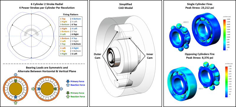
My engine is a six-cylinder, opposed-piston, cam-driven, two-stroke in which each cylinder produces four power strokes per revolution. This arrangement, shown in the left figure below, results in two cylinders on opposite sides of the engine firing simultaneously. The firing pair alternatives between a vertical pair and a horizontal pair. The middle figure shows the simplified CAD model I created for quick analysis of bearing stress. The model describes only two opposing cylinders in vertical orientation within the rotor assembly. The opposing pistons in each cylinder have been reduced to just their cam radius with a flat face to which 2,915 lbf (the product of my peak gas pressure and piston surface area) is applied. The bearing model (6202 selected without the 5x safety factor I mentioned in my last comment) was downloaded from the supplier and the material specified as ASTM 52100 bearing steel having 67 kpsi yield strength. All other materials are Maraging 350 steel with 295 kpsi yield strength (associated with 600F).

Picture1_iz8usb.png


The right figure captures the result of static stress analysis in which all components but the bearings are hidden from view. I have also hidden the outer hosing of the most healily loaded bearing so it's balls are visible. The top plot shows bearing stress when only one cylinder fires. In this condition, the peak stress on the bearing is 23,212 psi, 1/3 of the bearing material's yield strength, too low for long term fatigue life of the bearing IMHO. The lower plot shows bearing stress when the two opposing pistons fire simultaneously. In this condition peak stress falls to 8,376, about 1/8 of the bearing material's yield strength, likely adequate for long term fatigue life IMHO.

This quick study illustrates an important phenomenon. Note the hot spots above the bearing balls in the top stress plot and compare them to the widely distributed load on the outer shell of the lower plot. Even with twice the loading being applied to the central shaft and the rotor of my engine, the peak stress has fallen by a factor of 2.77. Factoring in the doubled load, that's a 5.54 x reduction in peak stress.
 
Peak piston face force of 2915 lb is REALLY low. Is this engine really small? (Yes I realized how tiny a 6202 bearing is)

Static analysis of a bearing like in the far right is going to be VERY difficult to justify for anything other than a not rotating condition. Resultant contact forces in an analysis like that is going to have more to do with the size of the elements (mesh) than anything attempting to replicate a real circular contact patch from deformation. I would suggest a 2d Symmetric FEA, because the amount of elements needed to make a full blown 3D analysis would be HUGE to say the least because the size of the real contact patch deformation is TINY. With that said... where did you get that 52100 Fty is 67ksi? Maybe dead soft annealed. It's closer to 295ksi in a usable bearing state. Static load isn't even the limiting factor in a bearing...usually. With that said with the numbers below it's exceeded the raceway static load capability.

Where did you get your 5x safety factor concept from? Again applied to above model... absolutely meaningless for bearing selection.

How long do you expect the engine to operate before bearing failure is THE problem:

Now I'm guessing I'm missing some aspects of operation of this type of engine... so just looking at Peak piston face force of 2915 lb, assuming the line of action is "small angles" to the center of the bearing I think you said it was a 2 stroke so I put it up to 11kRPM as a guess and I got 19 minutes before the bearing is at a 10% chance of failure life... not safe. Even if it's a model there is a lot of machining that's going into a project like this... those bearings loose it... that's going to destroy the engine. If it were me... I would cry. You got some work to do.

 
Work out my real world known example. 58mm bore, naturally aspirated, two 6207 bearings. If we use 75 bar peak cylinder pressure, I get combustion force of 20,000 N, ie 10,000 N per bearing.

This is a single cylinder engine with a balance shaft, so some of the mechanical balancing loads pass through the main bearings, but just look at the combustion loads.

From SKF, the basic dynamic load rating is 27 kN and static rating 15.3 kN. The limiting speed is 13,000 rpm ... engine redline is 11,000.

I get 40 hours rated L10 life at 8000 rpm (top gear at 100 km/h is in that range). Mine has about 60,000 km on it. Obviously the combustion load is only seen for several crank degrees once per two crank revolutions, and since the piston acceleration is opposing the combustion forces at high revs, that helps some, and since that part of the life equation has an exponent on it, it probably actually helps a lot. If the stated load is only seen for 10% of the operating cycle, that changes it to 400 hours rated life ... probably 40,000 km at wide open throttle. This bike is only ridden at wide open throttle ... it only has 12 horsepower. The MTBF life is much greater than the L10 life, and this calculation is probably rather conservative. Seems in the ballpark, though.
 
RoarkS,

Cylinder bore is only 1.078 in and stroke while ports are closed is only 0.342 in. Peak gas force is 3,057 psi (28:1 CR with max equivalence of 0.46), and max rotor speed is only 2,626 RPM (driving the propeller directly).

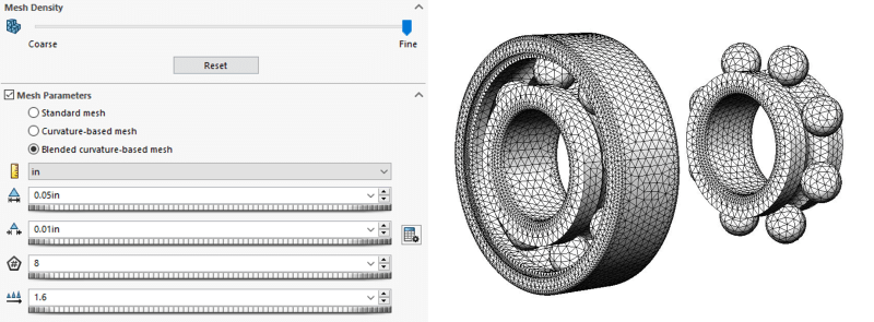
I understand bearings are dynamic devices. I used static analysis at the worse case condition to get a feel for the loads resulting from my opposed-cylinder arrangement with no mechanical imbalance (in theory). From the analysis, it's clear the arrangement has great impact on the stress on the bearing. The mesh I used isn't terribly coarse. The minimum element size (0.01in) was selected by Solidworks based on the minimum radius in the design. I only use 2D symmetric analysis when I need to. This particular analysis only takes about an hour to run on my analysis machine (12 cores/24 threats at 3 GHz), and I'm free to work on my other less powerful workstation while the analysis runs.

Picture1_stzqy5.png


I think I got the yield data from the "MakeItFrom" web site, but can't find where. Starting over, SKF says they use 100Cr6 which has 88 - 100 kpsi tensile strength in the hardened state according to MakeItFrom. Looking the same material up on MatWeb, however, results in 334 kpsi tensile strength and 247 kpsi yield strength. My mistake. I should have questioned the low number I found on MakeItFrom. I'll update my material properties per MatWeb.

The 5x safety factor was applied to the shaft diameter and I explained it's origin in an earlier comment: "In the cell where I specified the 5x safety factor, I have a note that says "required to force selection of the same bearing as the Honda GX200 engine which produces slightly greater HP and torque." The FEA analysis doesn't include that safety factor.

Since you are so quickly able to evaluate the performance of my bearings, I assume you have solved the problem of selecting yours. What bearing did you end up selecting?
 
Contact/Hertzian stress is what counts.
This link concerns itself with many combinations, but not quite Ball on race.

The bearing manufacturer's load ratings take that into account.
There are host of "factors" that need to be stacked up to properly de-rate the bearing and solve for a reasonable life estimate.
I'd pay close attention to The "fatigue" load, and the lube cleanliness factors.
 
No I haven't... because I'm still unsure of how to deal with the spike bearing load. Your worst case number is about as problematic as my worst case number... It's just I didn't think you were looking at the right issues and wanted you to analyze your system in the same terms I am for the sake of my thread. I'm still looking for how to justify how to treat gas load on bearing force.

Like Brian said "combustion load is only seen for several crank degrees once per two crank revolutions" He's absolutely correct... It's just I don't have a sound engineering source stating how to deal with that. Empirical on his bike is pretty tempting but I would LOVE to have a look at a Honda engine engineers design notes.

My references left me hanging in their explanation of going with an Average force instead of peak force for gas pressure.

If I work backwards from expected engine performance and use IMEP I get about 215 PSI as a "whole engine" average. If I take my gas pressure force from above and average... make a rectangle with the same area as the area under the curve I end up with 117 PSI. If I could justify using either of those two numbers instead of my peak 879.5 PSI that would make for what I would consider a "reasonable size" bearing for my packaging issues... and "looks right" when compared existing radials. All I'm doing is using Typical L10 life knock down ratings based on speed and load, along with a 2.0 "Extreme and indeterminate shock load" factor as Published in my Liston reference above.

One I haven't tried yet is only average the pressure for the crank angle range the pressure is "on the move". That would give me a little higher area average... probably a little more inline with IMEP.

Again, someone has to have figured out how to calculate this with a verified/published model. <- what I'm looking for.
 
RoarkS,

Barring manufacturing variance (which I cannot estimate at this point), my engine has no imbalance. It has only gas pressure, and because it is applied equally on opposing sides of the rotor, it is primarily manifest as uniform compression force on the outer bearing race and the shaft. From my FEA work these forces appear to be spread reasonably well across the bearing races.

I think much of the reason for confusion in regards roller bearings is the familiar engineering details are buried under ISO 281 standard language (aka "bearing parlance"). The NSK document "Dynamic Load Rating, Fatigue Life, and Static Load Rating" and the NASA document "Rolling Bearing Life Prediction, Theory, and Application" assist in understanding the basis of the language in normal engineering terms. I believe the averaging of load is justified under language relating to fatigue life not yield. That makes perfect sense IMHO insofar as peak loads are well under material yield.

In calculating your average force, don't forget much of the force on your pistons is translated into rotational force by the crank (or cam in my case). In my FEA runs (updated below with finer mesh and proper material properties), I assume the entire combustion event occurs at top dead center (detonation), the worst case (I obviously plan to control timing such that this doesn't occur, but it will likely happen now and then during testing). Note both plots below use the same color scale, and they clearly illustrate how little load is on the bearing races when opposed cylinders fire. Max deflection of any bearing component is 0.00047 in.

Picture1_yemr3x.png


I'm now off to see if I can express my calculated bearing loads into "bearing parlance" so I can relate it to normal bearing specifications.
 
EHudson

Mack and Shaw showed up today. Same story... completely hung up on calculation, assumptions, and equations that are completely unneeded with CAD analysis. In multiple places they made mention of maximum and mean forces but gave no recommendation as to their deployment in bearing selection.

They mention Caminez and Iseler 1923 as being "The basic method of determining bearing loades for internal combustion engines and maybe they expect the reader to go check that out?
Being a little newer than my other book, the IMEP and Peak forces are in line with what I am working with so I know I'm in the ballpark.

There was mention of a "time weighted average" but again no mention of how to deploy it. It almost sounded like they were talking about a time weighted average through 720°... which I don't understand why that would be different than local to one cylinder... maybe I read it wrong. But I'm willing to bet BrianPetersen and his Honda example (10 Jan 20 13:05) is probably pretty close to the truth.

Having gone and looked at large Radials in museums I cant imagine that N 314 ECP bearing isn't an adequate choice for the forward main bearing.

 
It may be worth looking at what other modern radial engines have done with respect to their crankshaft bearings.
Look for instance at the Clear Energy Systems patents, for example US8567354-B2

PJGD
 
PJGD Didn't see anything in the patent of interest to me... did you? They are local...

EDIT: I just talked to one of the project leads. It's a P&W engine core they were tinkering with. I've got a call out hopefully I'll hear from the engineers.
 
RoarkS,

Below is a condensed version of SKF's bearing selection guidelines. Note the first statement under "Equivalent Dynamic Bearing Load" which says "When calculating the bearing rating life..." This tells you all those calculations relate to fatigue life not yield strength. Now jump down to the last statement of the left page and not where it says "High loads acting for short times (diagram 4) may not influence the mean load used in a fatigue life calculation. Evaluate such peak loads against the bearing static load rating C0, using a suitable static safety factor s0." The page on the right summarizes that calculation. Note that it is tied to yield strength insofar as the 4,200 MPa value for the "basic static load rating C0" is that which produces permanent deformation of .0001 x ball diameter. This small deformation results from the fact that the 4,200 MPa value is greater than the 2,000 MPa yield strength of 100cr6 bearing steel. Reading further down the page, you see that the peak load with no deformation uses a minimum safety factor of two which brings the 4,200 MPa value down near the yield strength of 100cr6 bearing steel.

Recall that the stress in the bearing is associated with Hertzian contact between the balls and the races and calculating the associated stress is terribly complex. That's why safety factors are common. Since the [link engineeringtoolbox.com/factors-safety-fos-d_1624.html]typical safety factor for engine components[/url] is at least six, a bearing specification would limit peak bearing load to 4,200 MPa / 6 or 700 MPa (101,526 psi).

Bearing_Selection_f5emxy.jpg


Once you have the peak loads within the bearing's yield strength (derated by your chosen safety factor), you can go back to the "Equivalent dynamic bearing load" calculations on the left page of the figure above and use the results in bearing life calculations. I believe the "Rotating Load" calculation is most appropriate for engines, and it is not a simple average. I believe it instead approximates peak and average loads into a single figure. Since it's a fatigue calculation, however, a simple average likely won't cause too much trouble and may be common among experienced designers. In the end, I think you're going to want to keep peak loads below the derated static specification and equivalent dynamic load as required to attain the bearing life you desire.

In regards your confusion over "time weighted average through 720°," I would dispute the "time weighted" aspect in a crank engine (but not my cam engine) and assume the 720° figure relates to the two revolutions required to complete all four strokes (it would be 360° for a two stroke). In your case, you have five cylinders driving two main bearings, so I would calculate the min and max load through one revolution of the full engine then halve that figure for use in the equations for "Rotating Load."

P.S. I found the bearing discussion for MechDesigner (a cad program) to be the best I've seen thus far. It actually relates to calculations for a cam follower bearing, but it relates to any roller bearing and is clearly presented. The full set of SKF calculations tells the same story but is harder to follow IMHO. SKF does, however, provide several nice examples as well as some computer tools.
 
I didn't read this whole thread. Not all radial aircraft engines had rolling element bearings for crankshaft support. All large radial engines that I am familiar with did not use roller type bearings for the crank pin.
The most highly loaded bearing is the master rod bearing. And yes there is large multi row radial engine that used hydrodynamic crankshaft main bearings. No tapered roller bearings used for crankshaft mains.
All large aircraft radial engines used SAE 60 weight oil.
Section view of R-3350 Wright Turbo Cyclone, showing the 3 rolling element main bearings.
 
Status
Not open for further replies.

Part and Inventory Search

Sponsor