Eng-Tips is the largest engineering community on the Internet

Intelligent Work Forums for Engineering Professionals

  • Congratulations waross on being selected by the Eng-Tips community for having the most helpful posts in the forums last week. Way to Go!

main step for sismic FEA analysis on a pylon shape sculpture 1

Status
Not open for further replies.

sebfr1138

New member
Aug 19, 2016
13
FR
Hello everybody

I work as structural engineer for artist

usualy, the shape of the sculpture make that i don t need to do vibrating studies,
but today, i need to do a sismic study due to the "pylon" shape sculpture but i don't know how to proceed to do sismic study

I use (and know well) Catia and "Catia génerative part structural analysis" module but don't know how to proceed with sismic

so i somebody could guide me, it would be greatly appréciate

Thanks and have a nice day

Sébastien
 
Replies continue below

Recommended for you

Where will the sculpture be located, and what codes/laws do you need to follow for the installation?

----
just call me Lo.
 
Hello

it will be located in Bordeau, France. it is in eurocode 8 located in area 2 (low) Agr = 0.7m/s2

it s a very moderate sismic area but the sculpture is a kind of pylon with important mass on the top so, it could be quiet critical

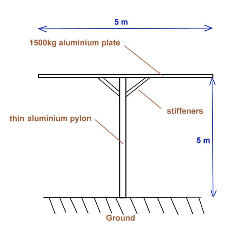
(it s a 5m high pylon with a 1500kg weight on the top )

thanks for your help

Sébastien
 
I'm not really sure what you're asking. Did you look at the code? What seems to be the problem? Could you sketch it so we know at least roughly the shape? What material is it made of?
It's low intensity earthquake (but check your national anex!) so you can make all the detailing as per non seismic code (Eurocode 2, 3, 5 or whatever, just check parts of eurocode 8 for simple calculations, for example, i know that for a concrete only thing you need to ensure is that your reinforcement is either B or C ductility class, it can not be of ductility class A. It's even written in 3.2.1 (4) section of eurocode 8 that if the acceleration is 0,08g or less it's low seismic area) and consider the earthquake as a normal force (if my quick calcs are right, the force shouldn't be larger than 3675 N (2,5*1,4*0,7*1500) where 2,5 is a coefficient for a plateau and depends on the fundamental period and 1,4 is a soil magnification factor(1,4 is the largest soil factor)). This is elastic force, you might reduce it by a factor 1,5, but I wouldn't do it unless necessary because it's a statue and I wouldn't want it damaged during such a small earthquake. That's basically a quarter of your vertical force and you apply it at the top. I think that's it. I hope I'm not oversimplifying this, someone correct me if I am.
 
Hello and thank you for your answer

i know that the load will be low but my configuration could have a low frequency natural vibration and i want to ensure that there is now way it could be damage, and in a second hand, i would like to learn to be able to compute other project in the future
the size of my pylon is limited (artistic work) and the matérial is cast aluminium

Sébastien
 
Sébastien,

I think that the code (EC8) doesn't offer any provisions for the design of aluminium.
I can't tell for sure how your structure will behave since you provided no sketch, but if it's one block heavier at the top I'd say it's safe to assume that it has 1 degree of freedom in each horizontal direction, lateral translation in x and y. This would mean that it's easily solvable even by hand calculations, a great book on dynamics is Dynamics of structures by Chopra.

Generally, if your sculpture is not one block or if it's not top heavy, you'd have a MDOF system and you could use rsponse spectrum analysis, but that's all explained in the book I mentioned.

Low frequency structures tend to have displacements similar to expected ground displacements. If you're doing an elastic design (which I'd suggest because of low forces and limiting the damage) you shouldn't have any problems design-wise.
Unfortunately, I don't know much about aluminum design so I can't tell you more specific things about detailing, but maybe some of the steel guys has an idea.
 
Hello and thanks you for yours answer

here a little sketch to better understand my concerns

the weight of the pylon would probably be around 500 kg

Image1_hvsxzb.jpg


so i have a heavy load on top of the pylon and with a simple modal analysis, i found some vibrating frequencies at 1.3 hz in torsion and 1.6hz and 1.8 hz in bending

that why i would like to investigate a little bit more in that direction

with fea Catia module "elfini" software, i could probably do all necessary computations, but i don t know how.

i wish that my sketch will help understanding.

Thanks a lot and have a nice day

Sébastien
 
I'm sure this is explained in detail in any dynamics textbook and I'm sure there are more guys here who know how to do it by hand better than I can, but I'm the only one here so I'll try to give you my view on it.
I did a quick model of something similar to what i believe you have (I added more weight on there to get relatively similar frequencies.

First, I'd suggest making your column a bit softer for bending to get the first two modes in translation (I varied the stiffness of the pylon to get the first mode as translation). You could also change the plate or maybe even the stiffeners, play with it.
I'm not entirely sure if it matters for simple structures like this one, so my instinct is to try to avoid it.

When you have the first mode as translation in x, and second in y you can do the following since it's simple SDOF system:
Go to the code and make a spectrum (figure 3.1). It'll look something like the thing on the bottom of my drawing.
Take the first frequency (or equivalent period) and find the value in the spectrum that correlates to that value of period (you can see in my drawing that the first period is 0,7 s and i got Se = 0,066 m/s2 for that period.
From there you multiply this acceleration with your mass to get the equivalent lateral force. This force is applied at the level of the mass (in your case at the top of the pylon). The rest is exactly like any other force.

You do the separate analysis for the other direction. You don't really need to do any complex combining of two directions because the forces will be small.

Now again, this is simple like this because it's SDOF and because torsional mode is pushed back (it's the third mode).

Another thing, note the exclamation points ! in my drawing. This last row shows me how much of the mass is activated in these first three modes. You can increase the lateral force by dividing the 1 with that number (if your software provides the mass) so in my case, I could multiply the end force with 1/0,75 = 1,333.

A good control of the fundamental period would in this case be (in my opinion) K = 3*EI/h^3 and T = 2pi*sqrt(m/k).

I hope this helped at least a bit and that I didn't misguide you in some way. For any more complex analysis I'd suggest that you invest in a dynamics textbook and read it. That's the best way to understand it.
 
 https://files.engineering.com/getfile.aspx?folder=aaac695d-4858-47ff-8439-07300bc5f5e6&file=drawing.png
Thanks a lot for theses explanations Hardbutmild
i try to apply that to my case and let you know later

Have a nice day

Sébastien
 
Status
Not open for further replies.

Part and Inventory Search

Sponsor

Back
Top