Continue to Site

Eng-Tips is the largest engineering community on the Internet

Intelligent Work Forums for Engineering Professionals

  • Congratulations KootK on being selected by the Eng-Tips community for having the most helpful posts in the forums last week. Way to Go!

Manhole design moments 2

Status
Not open for further replies.

Kinetic Savant

Civil/Environmental
Feb 28, 2021
6
I am trying to design a RC square manhole that is 4 m high and 1.8 m wide. I modelled the square 'tank' like manhole in SAP2000 and found the absolute maximum moment to be about 1.1 kN-m. However, when I used the formula for a fixed wall with one free edge from "Roark's formulas for stress and strain" or the same formula from Moody's "Moments and Reactions for Rectangular Plates" I get the maximum moment to be about 13 or 14 kN-m. Am I be modelling it wrong or is this big difference typical? If typical then why?

Thank you in advance.

Best Regards.
 
 https://files.engineering.com/getfile.aspx?folder=7ece7096-28c6-4cad-9d14-a3a23a372cee&file=SAP-150mmx300mm.PNG
Replies continue below

Recommended for you

You haven't mentioned what loads you applied on your manhole (COMB1) and how you applied them. When you say manhole I understand an underground chamber surrounded by soil. Under such conditions the moments would be an order of magnitude bigger (more like 100 kNm).
What are your structure loading conditions?
 
1.1 kNm over what height of slab? You need results in kNm/m or you need to know (and tell us) what height of slab resists the bending moment.
 
Thank you for your reply.

Kostast: Indeed it is an underground chamber, surrounded by soil. I have applied (to the walls from the outside) a triangular load that peaks at 57.62 kN/m2 and a factor of 1.7, such that (combo1) should be 97.95 kN/m2.

steveh: I am not sure I understood your point exactly. The maximum moment of 1.1 kNm/m is occurring at the bottom third of the wall.

I tried modelling the same by changing the bottom supports to fixed but the magnitude of the moment did not change much.

Also I tried using the formula for a simply supported wall with a free edge from "Roark's formulas for stress and strain" and I got a maximum moment of 2.9 kN-m/m which is closer to the results of the SAP2000 model, indicating that the model is treating the walls as simply supported. If so, can they be made to act as if they are fixed?
 

There are mistakes at modelling.. Notice that , Mmax = 1.846 kN-m. develops at bottom slab and the slab simply supported with pin and roller supports...

The bottom slab should be modelled with winkler springs and the walls should be loaded with active + traffic at one side , passive at the across wall vice versa..the load combinations for traffic vertical, soil , traffic horizontal , should be considered and the effects should be enveloped for design..
 
I think your mesh might be part of the problem. Unless I'm mistaken, your plate elements are spanning the full width of the short side. Try subdividing the elements into smaller squares.
 
Some advice; your copy of Roark should be stored away, like a precious jewel, only to be brought out in desperate occasions. All Roark (or his graduate assistants) did was grab formulas from published literature, like Moody or Timoshenko. Because of that, they had to leave out cases and ranges. Use the source literature instead.
And modeling a manhole on finite elements is fine, as long as all your assumptions are correct. But it's time consuming and like killing a fly with an ICBM.
Moody's has been a go to for 60 years. It is based on finite elements and has been vetted. If it gives you a result, you can take it to the bank.
 
Your results are way off then. Did you enter the geometry coordinates correctly? (In m, not mm) Pressure value in kPa?
 
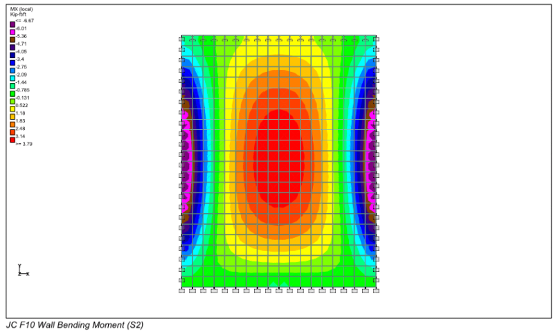
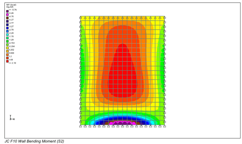
I would expect the moment contours to look similar to this. It looks like your wall mesh is only 1 element wide, so you aren't getting an accurate stress distribution.

MX_fyr51h.png

MY_flfiey.png
 
Thank you guys for your help. Indeed the issue was with what bones has said regarding the division of panels. I divided up the panels further and the numbers seem more reasonable now.

I do have another question now though, why is it that the stresses on the XY plane differ from those on the YZ plane. If everything is the same on all sides, shouldn't the behavior be the same on all sides?
 
 https://files.engineering.com/getfile.aspx?folder=1084272f-65a4-45c0-9f87-e01572da8736&file=SAP.png
Assuming you have checked the loading is applied to all four faces, in the correct direction, the problem looks like restraints at the bottom. Assuming there is a concrete base all the bottom nodes should be pinned, or if you have modelled the base with a single plate, that needs to be subdivided.


Doug Jenkins
Interactive Design Services
 
Thank you guys for making this forum so helpful!

Indeed Doug I had missed aligning the subdivision of the base with the walls. It is now behaving as expected.

Best Regards.
 
I should mention that the contours I posted earlier are based on the analysis of a single wall modelled by itself, with boundary conditions applied on all 4 sides. In this case the top edge was rotationally pinned and the other 3 sides rotationally fixed.

I analyzed the wall by itself (instead of the whole junction chamber box) so I could vary the boundary conditions between fixed and pinned. That way the range of possible stress conditions is enveloped.

If you want to do something similar with your SAP2000 complete box model, you can assign edge releases to wall elements to get simply supported behavior:
 
Status
Not open for further replies.

Part and Inventory Search

Sponsor