Continue to Site

Eng-Tips is the largest engineering community on the Internet

Intelligent Work Forums for Engineering Professionals

  • Congratulations SSS148 on being selected by the Eng-Tips community for having the most helpful posts in the forums last week. Way to Go!

Masonry on W section 6

Status
Not open for further replies.

Simlac450

Structural
Dec 2, 2022
30
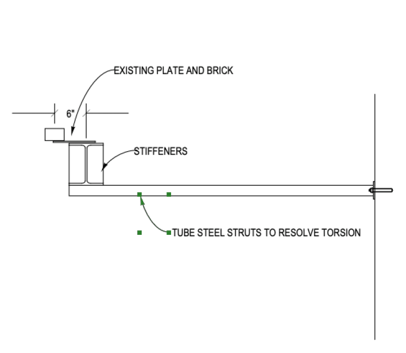
Hi guys, I am currently working on a old building where the owner had some issues with a W beam supporting one storey of masonry (mortar joint start to cracks), the masonry can’t sat directly on the beam so I add some stiffeners at each 16’’ c/c with a L section welded on them, but that will create a moment due to the eccentricity (around 4 kN*m), my W section is a W200x42. From the web to the middle of the brick I have 6 inches, when I evaluate the total stresses in compression I got 560 Mpa which is way above 350MPa (fy) and it seems overkill to increase my W section. One of my colleague suggests to ignore the eccentricity I would like to have your opinion on that.

Thanks
 
Replies continue below

Recommended for you

Its a torsional loading to the WF beam. I guess some people might hand have that but I think its prudent to design for the eccentricity.

The beam web stiffener plates will reduce the bending of the beam flange, but do not increase the beams torsional strength.

Not sure what check you ran, it isn't clear to me where there is compression due to this? I would look at the beam shear including the torsion, as well as beam bending stresses. AISC (pardon my americanness) provides equations for member strength for combined bending and torsion. (AISC 360-10 Section H1.2)

Now if the beam is locked into a concrete deck there might be a good load path for the torque to be taken out directly.

We spent a bunch of conversation on this a few months ago. Very similar condition. If I can find it I will post it back here.
 
I would not ignore the eccentricity. Can you add another beam adjacent to it?
 
What's above that vented soffit? If there's a diaphragm up there and the beam is adequately connected, then that could be used to resolve the torsion (driftLimiter mentioned this with the concrete reference, but it could be other materials with sufficient strength, stiffness, and connections as well).
 
Well from the other side I can see half of the beam, so best case, only the top flange is bolted on the diaphragm, that doesn't seems enough to control the torsion..
 
Simlac450 said:
only the top flange is bolted on the diaphragm, that doesn't seems enough to control the torsion..

Can't say I agree with you. Draw a section through the beam and then create a free body diagram. See what the beam is resisting and how.
 
alright, I'll check that, thank you y'all, I appreciate
 
Can you close up the section? Add side plates so that there is a box section? It doesn't have to be on both sides.
 
Yes I could do that, and it could be pretty straightforward to evaluate !
 
Creating a box section would probably resolve the beam torsion issue, but in addition, the end connections must be able to resist that torsion.
 
What about something like this...?

W_fhadre.png
 
I think it will change the look too much but if I put the hss somewhere between the flanges I think it could be good solution
 
Simlac450:
Pay attention to Hokie’s suggestions, they are right on the money. Additionally, you have to unload, untwist, the beam (reduce the stresses) by jacking it up on the loaded side before you do the additional work on it, in place. You shouldn’t normally be welding on a highly stressed beam, because it will just yield even more, due to the heat.
 
Weld a plate on the side of the W beam to turn it into a fabricated box.

W section (or to me, UBs) are often used with a plate on the underside but I can rarely ever justify them except for on very short spans (so brick arching very much in effect) and with the plate itself also bearing onto the support (so some torsion is taken out).

Edit - missed Jed's post above me
 
GTCE said:
Weld a plate on the side of the W beam to turn it into a fabricated box.

That will only work if there is enough torsional resistance at the ends of the beam. Hard to calculate that IMHO.
 
To get rid of the torsion at the ends, I'd unload the beam (you might need to use some jacks) put on the side plate(s) to make it into a box, then add a new clip angle at the ends to the side plate and brick (using epoxy to anchor to the brick). Carefully unload the jacks, looking for distress.
To analyze, resolve the torsion into a couple.
 
Status
Not open for further replies.

Part and Inventory Search

Sponsor