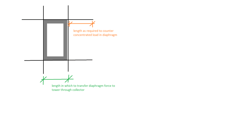
I am currently designing a small 3 story building that has 2 egress stairs at either end. Each stair is wrapped in masonry on all 4 sides. The stair dimensions are 8’-2” x 17’-0” (inside of CMU to inside of CMU). These stair towers are each 43’ tall +/-. Code is 2015 IBC.
The owner is wanting to use these stairs to resist lateral loads in the long direction (17’-0”). We have an ultimate shear of approximately 314 kips due to wind (mostly because of large parapets on the roof of the building).
I have never quite designed a stair tower like this before. Is there any design literature that goes through the process of designing a similar stair tower to act as a single unit? That is, to design this masonry stair tower almost as a tube sticking out of the ground with the short walls acting as flanges of a beam and the long wall acting as the web of a beam?
I have see plenty of building constructed this way, I am just not quite sure how they going about doing it, and if there is a simple hand calculation process (or if this is something that need FEM).

