Continue to Site

Eng-Tips is the largest engineering community on the Internet

Intelligent Work Forums for Engineering Professionals

  • Congratulations cowski on being selected by the Eng-Tips community for having the most helpful posts in the forums last week. Way to Go!

Masonry vault in-plane stiffness 3

Status
Not open for further replies.

hardbutmild

Structural
Aug 10, 2019
294
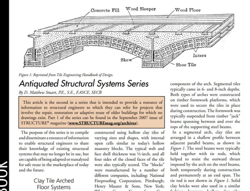
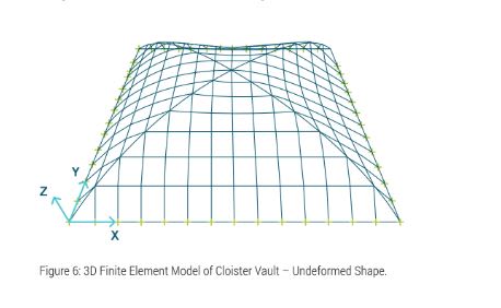
Does anyone have a book or an article suggestion where this is defined? I need to do a seismic design of a building that's over 100 years old and some floors are made of masonry barrel vaults. I'd like to learn more about masonry vault plates, but can't find any info anywhere. Some vaults span in x direction, some span in y, some are directly supported by walls, some lie on steel beams. I drew a quick sketch of typical building. Also, is there a way to model it like a plane element to get equivalent stiffness of the vault? I much prefer to use plane elements instead of curved ones.
sketch_vpt6fd.png


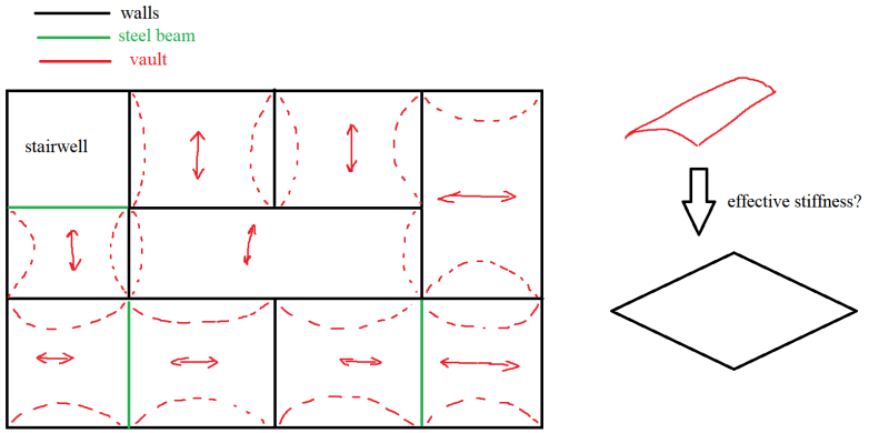
It seems like a rigid diaphragm to me, but I'd like to know how to theoretically determine if it really is a diaphragm. I know I could model it and check the deflections and force distribution, but a) I'd like to avoid doing that for every such building (different curvature of the vault, different material, different vault type like cross vaults...) and b) I suppose that modulus of elasticity is different in longitudinal and perpendicular direction of the vault and the brick layout should also influence the stiffness and I don't know how to determine the value of those stiffnesses.

I feel like there should be a fairly simple expression that enables me to model the curved element as the plane one with the equivalent stiffness.
 
Replies continue below

Recommended for you

1) I'd go with a rigid diaphragm as you said.

2) I'd astonished if somebody actually turned up something in print for the in plane stiffness of masonry barrel vaults acting as diaphragm.
 
This is the kind of thing that we're talking about, right? If there's a seismic concern, it's probably things jostling around and chunks of the arch falling out. That said, I don't actually know anything much about how these systems have performed in actual seismic events.

c02_zgxqjj.jpg
 
Thanks KootK, really appreciate it. I'll certainly check that article. That's the type of system I'm talking about, yes.
It's really frustrating how poorly URM is explained in standards and literature. It's either barely mentioned or it's fully scientific and impossible to implement in practice.
 
hardbutmild said:
It's either barely mentioned or it's fully scientific and impossible to implement in practice.

Happy to help. I've never thought about it in those terms but you're absolutely right. Why not just FEM the whole system in 3D? Kidding..

Honestly, the article that I posted the clip from will probably be useless to you. Nothing diaphragmy included there.
 
KootK said:
Honestly, the article that I posted the clip from will probably be useless to you. Nothing diaphragmy included there.
I've seen now that there's something like 10 parts on this topic on structure mag, it'll be an interesting read at least. There's usually no concrete in these slabs that I'm working with, that's why I'm a bit worried. Guess I'll try the good old "check it as both a rigid and flexible diaphragm".
 
Celt83 said:
Check the Carnegie Pocket Company on SlideRuleEra's site
Thanks! I'll search for it, this document looks great.
 
hardbutmild:

If you can find a copy of Jaques Heyman's The Stone Skeleton chapter four covers the analysis of masonry vaults. Also, John Ochsendorf's group at MIT has a lot of resources covering these structures: Link

Regards,

DB
 
DBronson,

Thank you for your suggestions. When I got the problem I instantly looked into the Stone Skeleton, it's an absolutely fantastic book. It's just that it doesn't really talk about this. I didn't come across the MIT resources before so I'll definitely check them. If not for this particular problem, they'll help with something else for sure.
 
I found it!

I just wanted to share with you that I found the article that addresses this question and it's free to download (just click on "descargar") here: On page 10 of the article it shows how much of it is bending and how much is diaphragm action (diaphragm action is about 66 - 75 % of the overall response). It's a double barrel vault so single barrel vaults are probably more to the bendy side (I assume).
 
The paper is interesting, and certainly better than nothing, but I question it's applicability to what you're doing. The cloister vault is a two way animal with shear wall restraint on all four sides. Your shallow arch floor is a one way system, at best, shear resistance perpendicular to the arch at the ends.

hardbutmild said:
There's usually no concrete in these slabs that I'm working with, that's why I'm a bit worried.

What is the construction above the arches? Gypsum? Unknown?

c01_v51fy4.jpg


c02_bvol7n.jpg


c03_lk5wco.jpg
 
KootK said:
but I question it's applicability to what you're doing
Absolutely, it's probably a bit more on the bendy side. Cloister vault is somewhat similar to a barrel one, but stiffened in the orthogonal direction. I know that the load path is different, but it feels like a cloister vault should be stiffer. Also, since barrel vaults are rarely square, it should become even less diaphragmy (I think).
But at least some method of calculation is given and now I can at least eyeball it better than before. Also, similar procedure could be done for a barrel vault if I really needed to do a lot of similar structures (I'd be more confident using a verified procedure).
KootK said:
What is the construction above the arches? Gypsum? Unknown?
Unknown, but I want to say that it's probably garbage. I have a feeling that they dumped everything they had in there (parts of old bricks, random rubble etc.) and just closed it with planks (obviously it's a bit better than that, but I don't believe that it's well built. Even if something resembling concrete exists it's probably of extremely poor quality).
 
You got the tie rods mentioned that antiquity article? End spans and interior?

Do you know if there's any grout in the masonry arches, either in your situation particularly or in general?

This was what I had in my head for your shear resistance mechanism parallel to the shallow arches.

c01_rwzuto.jpg
 
We tend to only think of in plane shear for diaphragms but, in reality, they always have to deal with in plane tension and compression. It is for these forces that I feel this system would be most challenged.

1) For in plane compression, I see the mechanism being as shown below.

2) For in plane tension, you should be in great shape if you have the tension rods; worse shape than the compression case if you dont.

c01_pauniq.jpg


Fortunately, most of these older buildings are pretty regular from floor to floor so you don't have a great need for transfer diaphragm capability..
 
KootK,
I haven't seen any tie rods, they usually exist in cloister vaults, but not in barrel vaults, since barrel vaults are either on both sides of a steel beam or on a thick wall (like in the picture I drew in my original post).
There's always grout in masonry, but it's usually lime mortar in bad shape.
Yeah, if it's something like what you drew, then it's more of a flexible diaphragm right? But arches rarely span between two steel beams (it's either between two walls or one wall and one beam, at least in standard residential buildings). I don't think a wall would shift like that, but then again, it might deflect slightly. I don't think that should be significant though.
 
The second way that you drew doesn't usually have flush beds, they are overlapped, just like head joints are displaced in a standard wall, not really vertical.
Also, I don't really follow the in-plane tension and compression thing. Isn't the last drawing out of plane bending?

Am I wrong for thinking that something like this picture would happen? my doubly curved struts are a bit silly, but I hope they convey my idea.
sketch_dixkwv.png


From this it looks that on the right We have a diaphragm, but between arches, now that's a real question I think.
 
hardbutmild,

You maybe interested in reading this paper. Link
 
hardbutmild said:
The second way that you drew doesn't usually have flush beds, they are overlapped, just like head joints are displaced in a standard wall, not really vertical.

Great. All the better for shear capacity and rigidity.

hardbutmild said:
Yeah, if it's something like what you drew, then it's more of a flexible diaphragm right?

I still think that it'll be closer to rigid but, truly, I'm no expert on shallow arch floor systems used as diaphragms. Just having some fun with it.

hardbutmild said:
Also, I don't really follow the in-plane tension and compression thing. Isn't the last drawing out of plane bending?

What I was trying to convey is that in plane diaphragm compression will ultimately be resisted by out of plane deformation of the arches. Like opening a pair of scissors and then closing them with lateral loads (your fingers) at the tips.

hardbutmild said:
Am I wrong for thinking that something like this picture would happen?

No, I agree that you should have healthy diaphragm action perpendicular to the arches. The week link is probably the friction mechanism between the masonry and the the steel beam that passes the shears from one barrel to the next.
 
Status
Not open for further replies.

Part and Inventory Search

Sponsor