psychedomination
Structural
- Jan 21, 2016
- 123
Hi there,
I’m working on a masonry residential project that has quite a few window and door openings. I’m trying to wrap my head around how to break the wall up into separate panels.
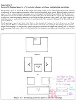
The British standard gives the following example :

However, I don’t fully understand the 2nd option. Why don’t those two top squares show any load distribution? Wouldn’t there be a line load from the window on their free edge? Wouldn’t they also be taking a wind load, therefore distributing that load to top, bottom and right? Or is the assumption that the whole top portion is an opening?
Is there any videos, text or books you can recommend that give more examples of this, where walls are broken in to sub panels due to openings?
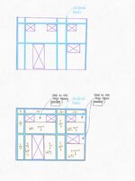
For my specific scenario, my walls and openings are as follows:

The project is using concrete masonry units. Wall panels will be hollow, the reinforced bands will be filled with concrete and reinforced as required. I know that adding sill reinforcement may simplify the panel analysis between the windows but it’s not really typical to put in sill reinforcement where I live, so I’m checking if it works without. Ideally, I’d like to minimize the strong bands if they aren’t needed.
In the British standards, it appears that it allows you to increase the panel overall UDL if a line load is present on a wall panel free edge.
I’d appreciate your thoughts. Is there a more efficient way to layout the strong bands and sub panels? Is what is proposed reasonable? Note lateral wind loads are quite high ~2.5 kPa. Vertical bands will be sized to take the wind loads to the diaphragm.
I’m working on a masonry residential project that has quite a few window and door openings. I’m trying to wrap my head around how to break the wall up into separate panels.
The British standard gives the following example :

However, I don’t fully understand the 2nd option. Why don’t those two top squares show any load distribution? Wouldn’t there be a line load from the window on their free edge? Wouldn’t they also be taking a wind load, therefore distributing that load to top, bottom and right? Or is the assumption that the whole top portion is an opening?
Is there any videos, text or books you can recommend that give more examples of this, where walls are broken in to sub panels due to openings?
For my specific scenario, my walls and openings are as follows:

The project is using concrete masonry units. Wall panels will be hollow, the reinforced bands will be filled with concrete and reinforced as required. I know that adding sill reinforcement may simplify the panel analysis between the windows but it’s not really typical to put in sill reinforcement where I live, so I’m checking if it works without. Ideally, I’d like to minimize the strong bands if they aren’t needed.
In the British standards, it appears that it allows you to increase the panel overall UDL if a line load is present on a wall panel free edge.
I’d appreciate your thoughts. Is there a more efficient way to layout the strong bands and sub panels? Is what is proposed reasonable? Note lateral wind loads are quite high ~2.5 kPa. Vertical bands will be sized to take the wind loads to the diaphragm.
Last edited:
