Eng-Tips is the largest engineering community on the Internet

Intelligent Work Forums for Engineering Professionals

  • Congratulations waross on being selected by the Eng-Tips community for having the most helpful posts in the forums last week. Way to Go!

Massive Changes to My Engine Design ! 1

Status
Not open for further replies.

RodRico

Automotive
Apr 25, 2016
508
US
All,

You may recall the challenges I was facing with installing a fuel injector in every cylinder of my engine; with a 49.5cc engine comprised of 6 cylinders, each was only 8.25cc and required a micro-fuel injector that had good enough spray pattern to yield a well mixed homogeneous fuel/air mixture. After working through the injector design, I decided the injector approach was simply too risky for a small engine such as my prototype. I thus went off to work up an alternate architecture using a single larger fuel injector to feed an intake manifold shared between all cylinders. This puts the fuel injector into the realm of components I can buy off-the-shelf.

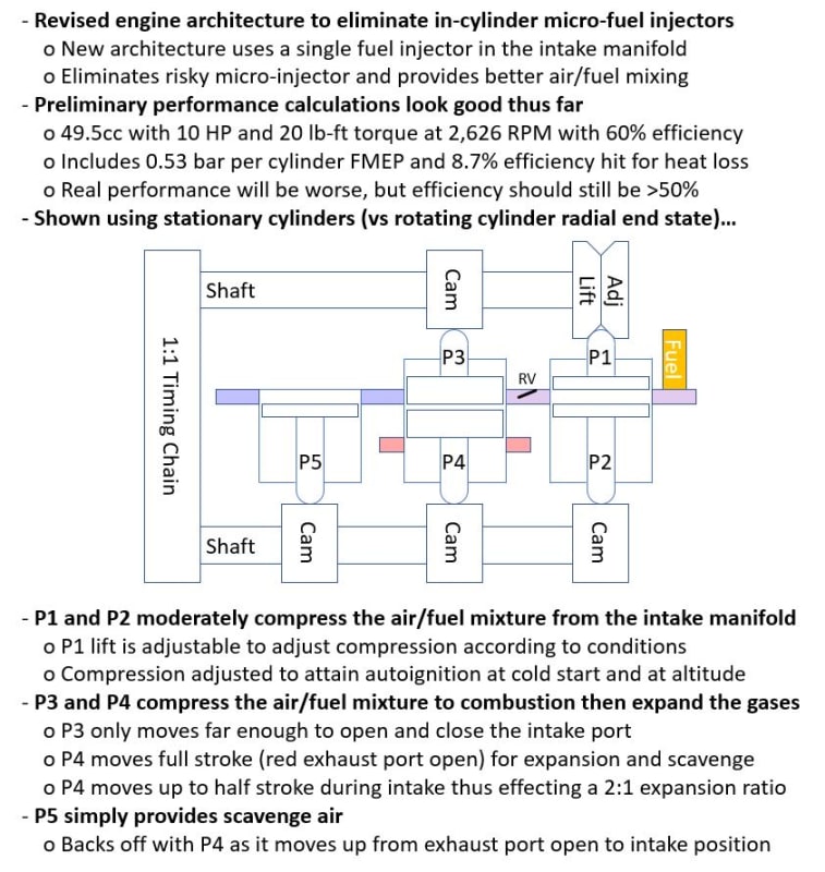
The use of a shared intake manifold with premixed fuel/air unfortunately requires use of two air pump pistons in place of the one in the prior architecture; one air pump piston for scavenge fed with air alone and another for intake fed with mixed fuel and air. The use of separate pistons increases complexity because each must now be driven by independent cam lobes (not a big deal) but the two pistons don't affect performance much because the pistons are very light and operate at comparatively low pressure. They do, of course add some volume, but not as much as I expected. Since I was reworking everything, I decided to exploit the separate cams on intake and scavenge to mechanize over expansion (to increase efficiency) and simplify the means by which I was compensating for cold-start and altitude (which both require variable compression ratio). All of these changes are evident in the annotated illustration below.

While I'm bummed at the amount of work this change is taking to update math models, CAD models, CFD, and FAE, I'm happy with the performance and glad to have caught the problems in the prior architecture *before* I started cutting metal!

Comments, suggestions, and questions are encouraged!

Rod

Capture_nhfzig.jpg
 
Replies continue below

Recommended for you

Ok that's all imformation very good to know. Yes i think you're right they don't need to be higly responsive. I feel as though I'm late to the party here, but it's good stuff.
 
Rodrico,
there is a market out there now for motors for self launching gliders in the 50 to 60 HP range, although electric motors are rapidly moving into that space. The major issue is the weight of the internal combustion engine which averages 55 to 90 lbs. If your engine can improve on that weight, you have a market.
Electric motors average 10 to 20 lbs., but that is offset by the weight of the battery packs.
B.E.

You are judged not by what you know, but by what you can do.
 
Berkshire,

If I had the engine in hand today, I would have many opportunities. The opportunities will diminish as breakthroughs in batteries emerge, however, and there will be plenty of time for that to happen before I have a product in hand.

The only markets I have faith in over the long term are those that can't depend on electrical infrastructure, and the largest market in that segment is military. Of course, we *could* see a breakthrough in bio-fuels (fuel from CO2 in the air, fuel from algae, etc.) during that time as well.

My original target, the US Army's RQ-7 drone and other such mid-size drones, still remains a favorite. The engine they use (a Wankel) has just been upgraded from 38 HP @ 7800 RPM to 50 HP. By my calculations, I can meet the power/weight and power/volume ratio of those engines while cutting fuel consumption in half and retaining better performance at altitude (due to my forced air induction). If the self launching glider market still exists when I have an engine in hand, I'll certainly sell in that market!

Rod
 
main-qimg-fb6304d4422c6c6083c03cbf746cf51e_crtscd.png

If you want to feel secure in spending your time developing this engine, you could perhaps project forward from the past trends in battery improvements. Perhaps ask a chemical engineer what the max possible energy per kg per battery is. It has been a while since I've taken chemistry, but I remember in some battery chemistries we currently have a lot of headroom for improvement in theoretical available power. Some of that has to do with how fast power is demanded, as lower amp draws can produce more total power output from the battery, temperature, etc.

I think it's impractical to think of something needing high power as being capable to extract a lot of the theoretically available power from today's batteries.
ZUMl8_s8okos.png


The pack could be oversized to be able to produce any desired amp draw for as long as they'd like, however, then you have added weight.

I know other considerations exist for engines.

One thing I considered for a while, was two strokes. Something like this:
scavenging_methods_aprjmx.jpg

applying the atkinson cycle:

could expand a given air fuel volume for a long time. With valves you could do variable valve timing whenever you wanted, and get full power whenever you wanted.

you already have a source of forced induction, this piston & crank case volume. You could more easily vary the volume of the crankcase with a plunger to vary the amount of air forced into the combustion chamber and to reduce pumping losses. You could do port or direct injection. you could do it mazda skyactiv style for efficient combustion.
 
It feels like growth in battery energy density is slowing, presumably because of the physics. There's a *lot* of money being thrown at improvement, so we should see better phone/laptop/auto batteries soon if physics can be overcome. It's also possible the physics mean the dream battery will be like fusion, just around the corner for decades to come. Only time will tell.

My engine is an opposed-piston two-stroke, and it uses the Atkinson cycle (or the Miller cycle depending on intake pressure). What makes it unique is the fact that it's a rotating-cylinder radial using HCCI. Because the engine block is a rotor, centrifugal force can be used to pump coolant, fuel, and air through the block. Permanent magnets can also be mounted on the rotor with coils in the rotor housing to effect a motor/generator for starting, reverse, and hybrid operations. All this is in my patent application (which *finally* made it to the top of an examiner's in-box last week).

A traditional crankcase induction pump is inefficient in normal use because it creates pressure that's unused and has significant transfer port volume. Moving air in an isobaric system requires work in proportion to volume and pressure (W = Pressure * DeltaVolume) with pressure determined by time (RPM and port area) and DeltaVolume defined by pump volume (the only changing volume). Minimizing pumping loss boils down to minimizing pressure (increasing port area) and eliminating unnecessary volume (pump clearance and transfer channel volume). Note if the pump and transfer channels are pressurized before the transfer and exhaust ports are open, then it's an isentropic system with work defined as AirMass * Cv * DeltaTemperature which yields much larger numbers than the isobaric calculations. Whether isobaric or isentropic, the pressure built up in the induction system is not expanded, the work required to compress the intake charge is lost, so it's best to minimize pressure and the dead volume in the pump and transfer channels. This is why multi-cylinder two-strokes are often arranged such that the pump under one piston charges another piston whose transfer and exhaust ports are opening just as the pumping piston begins its downward stroke.

Mazda Skyactive X is a clever end-around of the problems associated with controlling HCCI, but has a *lot* of unique parts (as do all modern 4-stroke engines) and only uses HCCI under low load conditions. My engine has far fewer unique parts and uses HCCI under all conditions. Their engine has the advantage of working while mine has yet to be built, however. [smile]
 
man, those are some genius ideas really. I was thinking if you were to do it mazda style, you could have the centripetal acceleration keep a rich air fuel mixture right by the spark plug, and have the remainder a lean homogeous charge. It would certainly be difficult this way, with rotating cylinders. The mazda engine uses a very specific coil design that I've had a lot of frustration with in the past. The coil senses the exact right time to fire for each cylinder, or rather, it senses if it were a fraction of a degree of on the last ignition event and adjusts accordingly. A bad coil made the engine think it could continue to advance the ignition timing past a safe leve. sounded like it had rod knock, the sensor portion was bad.

Your idea sounds genius because you can do away with all that wiring on the rotating cylinders, is this correct? will you put glow plugs on them, even? and the water pump idea sounds good, less complexity.

I should elaborate slightly on what my goal would be with my idea. It'd be similar to yours, I was even thinking of the hybrid setup. If you could make a new two stroke that met all the emission requirements, that'd be awesome. The hybrid system could provide the needed low end boost. And be the starter motor. The honda ruckus, honda insight, and now the honda CBR600RR all do this. Except only the insight is a hybrid.
 
I may see some stratification of the charge due to the fact that it is essentially resident in a centrifuge. This may slow HCCI heat release, but not by much.

I don't use glow plugs, though I do anticipate using block and intake air heaters for starting at cold-soak temperatures below 0F.

Meeting the emission requirements in a two stroke is non-trivial, but I think it's possible. The primary challenges are lubrication (no fuel/oil mixing, no ring oil passing out the exhaust port) and scavenge/intake (scavenge with clean air only, inject fuel only after the exhaust port is closed).

My patent notes the integral motor/generator provides starting, low end torque boost, silent running (important in military drones), and reverse. It would also, of course, charge batteries when the engine is running on fuel.


I imagine the US government is immune from emission requirements. Don't they use a dirty old wankel engine?

the idea I had for the engine in my mind would also use the hybrid function for a low end boost. Then, it could use the charging feature to dull the hit of the powerband while recharging the battery. Variable valve timing could keep the exhaust valve open during engine braking so a lot less power is absorbed by the engine, and goes to regen.

Motorcycles typically have lots of accel and decell events around a race track though, so not so similar to your application.

will yours directly drive ducted fans and props? I imagine an aircraft may not need a lot of low end power.

One thing you may or may not have considered is oil pooling on the bottom of pistons, and oil getting flung to the outside of the engine. Is there a cam on top? I just imagine that'd be something to overcome. I would think that's why lots of radial aircraft engines use push rods. It's hard to imagine without a more elaborate sketch.
 
Yes, the military is exempt from emissions and they currently use a Wankel. My other market, civil aviation, is also pretty lax in emissions (still flying leaded gas), and I aim to address that shortcoming.

Variable valve timing in my engine is accomplished by rotating the cams. Beyond that, I won't look at hybrid operations or reduction of motoring losses until I have a working engine that shows promise.

Yes, I will drive ducted fans and props. Though there are many drawbacks and risks associated with a cam driven engine, there are a number of advantages as well. One of them is the ability to complete multiple cycles per revolution, and this acts like the reduction gear commonly used with propellers (which are most efficient between 2500-2700 RPM). I plan four cycles per revolution at 2,626 RPM which yields the desired propeller speed even though the mean piston speed is comparable to 10,504 RPM.

You can see illustrations of the *concept* as it stood two years ago at . I've learned a lot since then so a lot of the numbers are different today, but the figures and brief description still convey the concept. Today, an engine sized to 95 HP at altitude would displace 385 cc, never exceed 220 bar peak pressure, and be between 55% (altitude) and 57% (sea level) efficient.

There is no sump in my engine. Oil is pumped by centrifugal force, a miniscule amount injected between the rings on every cycle, and fed to felt wipers that keep the cams lubricated. Circulating oil is also used to cool the cylinders.
 
that's all cool stuff, it looks like you've been thinking about this for a long time, and it shows.

I'm curious what type of analysis you've done for forces on certain components. Honda uses a type of plastic cams in their utility engines/lawnmowers, I believe the GC or GX series, that requires very little lubrication. There's no oil pump to take the oil up there, some just gets carried up on the belt, or flung up there.

May be enough for a prototype atleast. When do you think you'll be able to make a prototype? is it a single piece, i guess, piston housing/piston case/crank case?

I went to a trade school for a little while for machining. They were pretty bad at keeping us busy with projects, the good students atleast. Sometimes, people came in with something cool, and if they gave the materials, the instructor would usually say go ahead. You may find some luck doing this. It's hard to say without seeing everything if it could be done on basic stuff like they had where I went.

for the main case, (what would you call it?) Looks like a minimum of a mill, a rotary axis, boring bars, end mills, face mills/fly cutter, and they're probably not getting into engine specifics in most trade school maching shops so you may need to home it out, or get final finishing on the bores somewhere else.

Probably one of the hardest parts is going to be getting your stock over there. that's going to be a heavy piece.
 
michaelwoodcock,

My Excel analysis loop is thermodynamics -> mechanical instantiation with preliminary stress -> thermodynamics of the instantiated design then repeat until I'm happy. I then export all the key dimensions to a text file imported into a Solidworks parametric model where I do FEA over temperature and CFD.

The loads on the main cylinder cams, pistons, rings, and liners are high and cams prefer very hard surfaces, so they are made of Maraging 350 steel (which machines like 4340 steel when in the annealed state but gets very strong, tough, and hard once heat treated). The loads on the air pump cams, pistons, rings, and liners are low so they are made of Vespel, a strong self lubricating polyimide. All materials are available on-line.

Once the larger loop including Solidworks is complete, I will start setting up tool paths using Solidworks 3 Axis CAM and Fusion 360 4 Axis CAM and tweaking the design until I'm happy it can be machined. I have a 4 axis DSLS 3000 Mill that I will use to machine the first model. I will start by machining the parts in clear acrylic just to convince myself the design can be machined. I will next attempt it in actual metals, though I don't have much confidence I'll be successful on such a small mill... I'll likely have to take the work to a local machine shop in the end, but hopefully I will have eased their task (and saved some cash) by walking it through the whole process in softer material first. I will start fabrication of the clear model this year and don't expect to start the metal engine until next year at best.

One reason I'm making such a small prototype is so that it can be easily transported. I ultimately plan to make a dyno using a model aircraft motor (in normal mode for motoring while I capture pumping and friction losses and in generator mode with programmable load when measuring my engine's torque over RPM and altitude). The entire set-up will be small enough I can afford to box it up and ship it to 3rd party testers.

Rod
 
Status
Not open for further replies.

Part and Inventory Search

Sponsor

Back
Top