Eng-Tips is the largest engineering community on the Internet

Intelligent Work Forums for Engineering Professionals

Matching sampling velocity to average process fluid velocity

Status
Not open for further replies.

Muud

Materials
Nov 29, 2017
44
0
0
NL
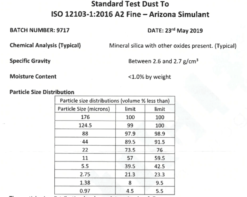
I am trying to measure the no. of suspended particles in water using an inline particle counting sampler. The process setup looks as below:

sampling_setup_gi2u48.png


To get a representative sample, the sampling process should be isokinetic. However, the sampler intake rate is fixed at 25 ml/min leading to an average sample velocity of 14.74 mm/sec. Comparatively, the fluid flow rate is much higher e.g. 10 m3/hr leading to an average velocity of 982.4 mm/s. It's not possible to change the sampler flow rate due to various reasons.

The sampler pump can't handle such high flow rates
The sampler is calibrated according to an ISO standard at this flow rate
The process fluid flow rate for different applications is different

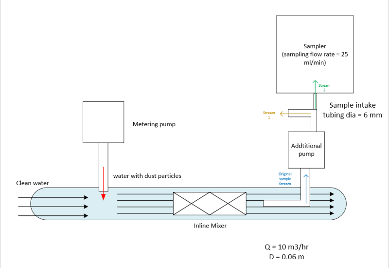
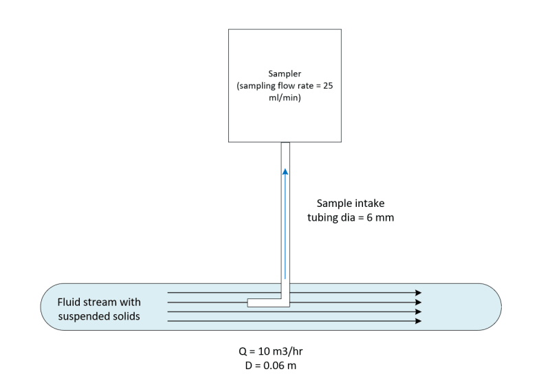
So what could be done to overcome this challenge? I was think about using an additional pump before the sampler with higher flow rate (to match the average velocity) and then dividing the sample out into two branches. One stream handles higher flow and another smaller branch with flow rate matching the sampler pump intake. Something like this:

sampling_setup_2_nozvzi.png


Is this a correct approach to solve this problem or some better approach could be adopted?
 
Replies continue below

Recommended for you

I agree with LI, assuring that you are really getting a representative sample is the first issue.
I find it hard to believe that the center 1% accurately matches the entire flow.
If there is another reason why you cannot use an inline method, then your 'over sample' method will work.
Why do you need a pump? with that flow the pressure in the line must be significant.
You should be able to allow flow out a sample line with your metering pump drawing your analysis sample off of this flow.
This is similar to how a lot of gas analysis work is done.

= = = = = = = = = = = = = = = = = = = =
P.E. Metallurgy, consulting work welcomed
 
@LittleInch

This sampler is infact supposed to work inline and measure the particle counts. But with the difference in the sampling flow rate and the test flow rate (mentioned in the drawing) I suspect we wouldn't have representative sample unless we do isokinetic sampling

Regarding the mixing homogeneity, there is an inline mixer just before the sampling point, so in principle the particles should be well distributed. Here is the sketch with additional items:

sampling_setup_3_sgxeef.png


Test particles are actually ISO standard test dust with following sizes and size distribution:

Dust_particles_ujtzh7.png
 
@EdStainless As mentioned just above, this is an inline sampler and the intention of this oversample method is to overcome difference in sample flow velocity and the main flow velocity.

And that is exactly why I plan to use to a pump. The pressure might be sufficient but the pump will ensure that we draw the sample at a rate that corresponds to main flow rate ( i.e. sample flow velocity = main flow velocity)

Yes, the sample could be extracted from the dosing pump but as you see in the new sketch above, there is an inline mixer. So sampling at this point would also give us an idea about the mixing / homogeneity (provided we can extract a representative sample)

 
I just think that it makes no difference.

The sampler with a 6mm tube only takes it in a 14.5mm/sec.

So having a second system which is still going faster than 14.5mm/sec makes no difference.

Why do you think matching sample velocity to actual velocity is important? The sampler will only take in a certain flow regardless of how you collect the sample.

And it shouldn't matter anyway. Key thing for me is to make sure your sampler is as close to the sample point as possible.

Still think a turbidity meter would be better...

Remember - More details = better answers
Also: If you get a response it's polite to respond to it.
 

The intention is to draw a sample isokinetically so the depending upon the main flow rate the sample flow rate should be adjusted. This ensures particles of different sizes will be drawn in the sample and avoid oversizing (more bigger particles counted) or undersizing (more smaller particles counted)

With this oversampling approach, the original sample stream will be drawn at required flow rate (for isokinetic sampling) using a pump. At this pump outlet, the flow will be divided into two streams. The stream that goes to the sampler will indeed have a velocity of 14.5 mm/sec and other stream at a higher velocity. I will try to clarify what I mean by assuming the following data:

main flow rate = Q = 10 .3/hr
main flow velocity = Vm = 983 mm/sec

sampling flow rate = q = 25 ml/min
sampling flow velocity = Vs= 14.7 mm/sec

To match the velocities, the additional pump will draw the sample at 983 mm/sec and this flow will be divided. One stream (6mm tubing to the sampler) will have a flow velocity of 14.5 mm/sec. The second stream velocity would then simply be the difference of original stream velocity (undivided) and sampler stream velocity. i.e. Vm - Vs = 983 - 14.5 = 968.5 mm/sec.

Would this work?
 
I think you still run into the same issue which is that your sample stream is going to be at a different flow velocity to the over sampled flow. Any attemtp to "divide" the flow will result in unequal volumes of solid material.

Only if you get the water flowing past the sample intake tube to be 14.5mm/sec will this idea work, but then I guess the solid material will start to drop out.

Can't you just measure the amount of standard test dust you're injecting into the water instead?

Remember - More details = better answers
Also: If you get a response it's polite to respond to it.


To clarify, "Only if you get the water flowing past the sample intake tube to be 14.5mm/sec will this idea work, but then I guess the solid material will start to drop out", you mean the 6 mm tube here, correct?

Since the sampler has a pump that maintains the flow rate, the sample velocity in the 6 mm tube should be 14.5mm/sec.

This is still just an idea but I was thinking about using a dividing manifold to divide the flow. But I am not sure if unequal flow dividing manifold exist or need to work with parallel/equal flow dividing manifold?

And what exactly do you mean by "the solid material will start to drop out"?

We measure the amount of test dust being injected, but in this case, we want to measure the counts of various particles sizes. The test dust specifications provide only the size distribution on volume basis and not on weight basis. So unless we count the particles of different sizes, we don't have much choice.


Yes the 6mm tube. What I mean about drop out is that the particles appear to be heavier than water. At low velocities they may start to drop out of suspension or become a different concentration at the bottom, starting with the biggest ones.

Can't you just assume the particles are circular balls or square cubes and calculate the weight from that?

I really don't think anything you do will give you the data you are trying to find by sampling this way

Remember - More details = better answers
Also: If you get a response it's polite to respond to it.
 
Status
Not open for further replies.
Back
Top