Eng-Tips is the largest engineering community on the Internet

Intelligent Work Forums for Engineering Professionals

Max Beam Reporting

Status
Not open for further replies.

SoFloJoe

Structural
Apr 3, 2018
76
0
0
US
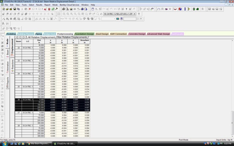
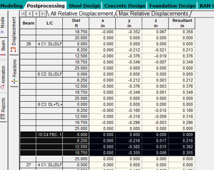
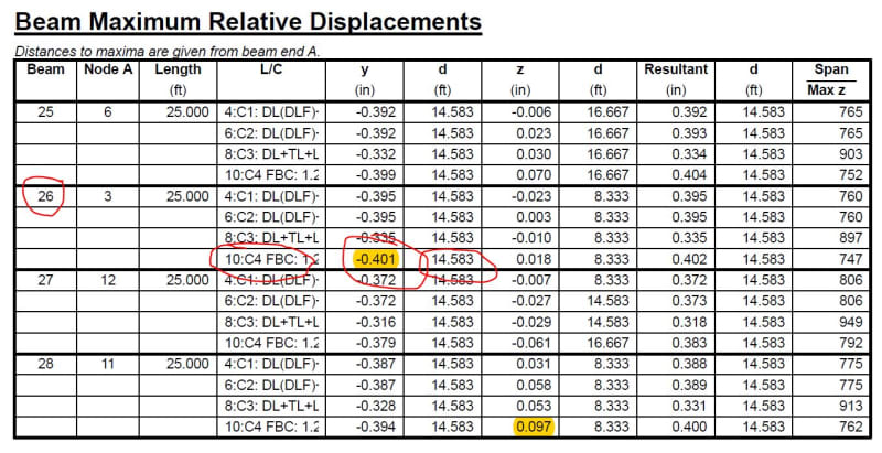
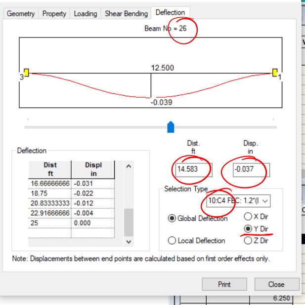
I have a STAAD model and I am analyzing it for deflections and moments. I have 3 different types of beams/columns with varied lengths. I am trying to create a report to give me the maximum deflections per beam type and lengths. I already did the beam displacement summary but this only gives me the maximum disp. on the whole model and not per beam types and lengths.

Is there a way to setup a report to give these maximums per beam without manually going through each beam?

Thanks for your help!
 
Replies continue below

Recommended for you

You could put those joints into a group and use the print command to output those displacements in the post-processing.

There is also a PRINT SECTION DISPLACEMENT command. But that may be more than you want.

By far, one of the easiest ones is the DFF command (you have to define the joints you are spanning between). Then it is quickly checked as a unity ratio.


Thank you. I created a range and it worked that way.

Now I have another question, I printed out the report of the "Max Relative Displacement" for a particular beam. I also did a beam analysis, but the numbers do not match. Does anyone know why? On the report it gives me a max displacement of 0.401" but on the beam analysis screen it only gives me 0.037" which is a factor of 10 difference. I also tried changing the setting from Global to Local deflection and it did make a difference but not by much.

Can anyone give me insight as to why they are different and the difference between global and local deflections?

Thank you!

180822_01_zpo7pj.jpg


180822_02_ionw45.jpg


180822_03_vvidiz.jpg
 
I think the 0.037" is the beam's deflection based on the load on it (by itself). The max. relative displacements is the displacement at the node(s) + the beam's deflection (for the total).
 
I am getting a warning about downloading it (from my Malware). Can you attach it to a post or (preferably) cut & paste the edit file into a post?
 
STAAD SPACE
START JOB INFORMATION
ENGINEER DATE 13-Jun-18
JOB NAME Eng-Tips Shared File
END JOB INFORMATION
INPUT WIDTH 79
UNIT FEET KIP
JOINT COORDINATES
1 0 0 39; 2 0 15 39; 3 20 15 39; 4 40 15 39; 5 60 15 39; 6 60 0 39; 7 20 0 39;
8 40 0 39; 9 0 0 0; 10 0 15 0; 11 20 15 0; 12 40 15 0; 13 60 15 0; 14 60 0 0;
15 20 0 0; 16 40 0 0; 17 30 15 0; 18 30 15 39; 19 17 15 0; 20 17 15 39;
21 17 15 2; 22 30 15 2; 23 17 15 7; 24 30 15 7;
MEMBER INCIDENCES
1 1 2; 2 2 20; 3 3 18; 4 4 5; 5 5 6; 6 3 7; 7 4 8; 8 9 10; 9 10 19; 10 11 17;
11 12 13; 12 13 14; 13 11 15; 14 12 16; 15 17 22; 16 19 21; 17 21 23; 18 22 24;
19 23 20; 20 24 18; 21 20 3; 22 19 11; 23 17 12; 24 18 4; 25 6 4; 26 3 1;
27 12 14; 28 11 9;
DEFINE MATERIAL START
ISOTROPIC STEEL
E 4.176e+006
POISSON 0.3
DENSITY 0.489024
ALPHA 6e-006
DAMP 0.03
TYPE STEEL
STRENGTH FY 5184 FU 8352 RY 1.5 RT 1.2
ISOTROPIC MATERIAL1
E 4.28151e+006
POISSON 0.292124
DENSITY 0.490173
END DEFINE MATERIAL
MEMBER PROPERTY AMERICAN
15 TO 20 TABLE ST W12X40
1 5 TO 8 12 TO 14 TABLE ST HSST5X5X0.125
2 TO 4 9 TO 11 21 TO 24 TABLE ST W14X68
25 TO 28 TABLE ST HSST6X4X0.125
UNIT INCHES KIP
SUPPORTS
1 6 TO 9 14 TO 16 FIXED
2 TO 5 PINNED
UNIT FEET KIP
CONSTANTS
MATERIAL MATERIAL1 MEMB 2 TO 4 9 TO 11 15 TO 24
MATERIAL STEEL MEMB 1 5 TO 8 12 TO 14 25 TO 28
LOAD 1 LOADTYPE Dead TITLE DEAD LOAD
SELFWEIGHT Y -1.25
LOAD 2 LOADTYPE Live TITLE TROLLY LOAD
MEMBER LOAD
15 TO 18 CON GY -4.16
LOAD 3 LOADTYPE Live TITLE LIVE LOAD
MEMBER LOAD
15 TO 18 CON GY -0.45
LOAD 5 LOADTYPE Live TITLE LIVE LOAD + TROLLY LOAD
MEMBER LOAD
15 TO 18 CON GY -4.61
LOAD 7 LOADTYPE Mass TITLE SKEW FORCES
MEMBER LOAD
15 CON GZ 1.84
20 CON GZ 0.76
LOAD 9 LOADTYPE Mass TITLE COLLISION FORCE
MEMBER LOAD
15 CON GZ 3.93
16 CON GZ 3.93
LOAD 11 LOADTYPE Crane Hook TITLE TROLLY MOVEMENT FORCES
MEMBER LOAD
2 9 CON GX 0.8
19 20 CON GZ 0.09
LOAD COMB 4 C1: DL(DLF)+TL(DLF)+LL(1+HLF)+IFD
1 1.18 2 1.18 3 1.15 5 0.064
LOAD COMB 6 C2: DL(DLF)+TL(DLF)+LL(1+HLF)+IFD+SK+TMF
4 1.0 7 1.0 11 1.0
LOAD COMB 8 C3: DL+TL+LL+CF
1 1.0 2 1.0 3 1.0 9 1.0
LOAD COMB 10 C4 FBC: 1.2*(DL+CF+SK) + 1.25*(LL+TL)+1.1*TM
1 1.2 5 1.25 9 1.2 7 1.2 11 1.1
PERFORM ANALYSIS PRINT STATICS CHECK
PRINT MEMBER FORCES LIST 1 TO 24
PRINT SUPPORT REACTION ALL
LOAD LIST 4 6 8 10
PARAMETER 1
CODE AISC UNIFIED 2005
FYLD 5760 MEMB 1 TO 24
PERFORM ANALYSIS
PARAMETER 2
CODE AISC UNIFIED 2005
CHECK CODE MEMB 1 TO 24
PERFORM ANALYSIS PRINT LOAD DATA
PARAMETER 3
CODE AISC UNIFIED 2005
FYLD 7200 MEMB 25 TO 28
FINISH
 
I'm not getting that displacement on my end. So I'm not sure what the deal is. (See pic below. In case you can't read it, the biggest displacement in the "y" direction is 0.048".) The brace runs between a node that is fixed and one that is pinned.....and it is not loaded in between in any load case (except for self-weight).

By the way (just a bit of constructive criticism here), one thing about this model that bothers me is having a load combination # that is lower than a basic load case. (Your highest basic load case is #11, but you are starting your combinations at #4. That just kind of bugs me 'cause it goes against STAAD etiquette. (If there is such a thing.) You are also repeating the same design parameters.

8.27.18_vlvrtk.jpg
 
That is weird. I just pulled the same screen up and I have -0.355" as the max in the y. I do notice that your distance is in ft while mine is in inches. But we both have inches for the y column but yet we get different results?

Yes, I agree with the load #s, I could not figure out how to change them without going into the edit file. It was how I initially entered them in. So should the load combinations go first 1-4? and then the individual loads after? Thank you for the insight!

10828_01_w8xkea.jpg
 
I do notice that your distance is in ft while mine is in inches. But we both have inches for the y column but yet we get different results?

Actually that is reversed: my distance is in inches.....yours is in feet.

Yes, I agree with the load #s, I could not figure out how to change them without going into the edit file. It was how I initially entered them in. So should the load combinations go first 1-4? and then the individual loads after?

That's also reversed. You always have the basic cases (i.e. dead, live, etc) first.....then the load combinations (i.e. D+L, etc).

I would think you could change this in the edit file fast.....but I doubt it would change your outcome....like I said: this is just STAAD etiquette.


Status
Not open for further replies.
Back
Top