Continue to Site

Eng-Tips is the largest engineering community on the Internet

Intelligent Work Forums for Engineering Professionals

  • Congratulations MintJulep on being selected by the Eng-Tips community for having the most helpful posts in the forums last week. Way to Go!

Maximum Demand KVA measured at transformer primary and secondary 1

Status
Not open for further replies.

edison123

Electrical
Oct 23, 2002
4,465
I have a sanctioned demand of 100 KVA and my transformer is 250 KVA.

The utility energy & MD meter is on the transformer primary side (11 KV).

I want to connect a MD meter on the transformer secondary side (415 V) for cross verification.

I understand the KWHR units will differ from primary to secondary by transformer losses.

But what about maximum demand (KVA) measured at 11 KV and 415 V sides? Will they be different because of transformer demand? If yes, by how much the MD measured at transformer primary will differ from the MD measured at transformer secondary?


Muthu
 
Replies continue below

Recommended for you

Thanks, Bill.

Wouldn't the no-load KVA of the trafo remain almost the same regardless of the time taken given the minuscule but constant no-load current and the constant no-load losses, both iron and copper?

The readings in the past two days

Date/Time/KWHR/KVA MD/Present PF/Cumulative PF
29.07.19/8.40 am/950.18/43.8/0.885/0.896
29.07.19/7.00 pm/952.16/43.8/0.888/0.899
30.07.19/8.40 am/953.91/43.8/0.868/0.893

I have no idea how the present and cumulative pf's are calculated by the utility digital trivector meter. Neither did the utility engineer, who knows only to read the meter.

I have already planned for transformer primary side metering mirroring the utility metering so that it's a direct one to one comparison, especially the KVA MD and the PF's.

Thanks, prc.

I understand the j part of the equation, which is the assumed percentage of KVA. How did you arrive the real part as 0.8?

Do you know the reputed 11 KV CTPT metering trafo suppliers in India? For me, accuracy and long-term reliability of the CTPT unit is more important than the initial cost.

For primary side 11 KV metering, what would you recommend, 3 VT, 2 CT or 2 VT, 1 CT combination?
Class 0.2 or class 0.5?
Recommended CT and VT burdens for metering?
Sorry for lot of questions.

I already have a few reputed manufacturers for digital MD controller plus Trivector meter, which will take care of protection (against MD overshoot and current OL).


Muthu
 
Muthu said:
Wouldn't the no-load KVA of the trafo remain almost the same regardless of the time taken given the minuscule but constant no-load current and the constant no-load losses, both iron and copper?
Background:
I once sent some students to the lab to verify the nameplate %imp of some small transformers.
They went through the setup and testing but were not asked to load the transformers to eat them up prior to the testing.
The results did not agree with the nameplate values.
The explanation was that the factory tests were done with the transformer at operating temperature and with the cold transformers.
The cold windings had a lower resistance and so the current was higher and the indicated %imp was lower.
When we factored in the temperature constant of the copper, the results agreed well with the nameplate values.
Of course with lower resistance and higher current, the KVA was higher.
In your case, I assume that the transformer was hot when you started your testing. As the transformer copper cooled, the resistance dropped and the current and the KVA increased.
If the primary voltage drifted up at the same time that would also increase the KVA.
s for the cumulative PF.
My thought that the values are too small to be credible.
Rational: The accuracy of digital devices is often given as a percentage Plus or Minus one count.
If the values are very small, the plus or minus one may introduce a noticeable error.
To get accurate values at those low levels you must first verify that you are in a linear portion of the metering transformers.
Then either use analogue meters or ensure that the digital meter is using enough counts at that low level that the plus or minus one count is not affecting your accuracy.
I would hesitate to make a financial decision based on those no-load numbers.


Bill
--------------------
"Why not the best?"
Jimmy Carter
 
Bill

Given that trafo no-load current is constant, wouldn't a colder winding with lower resistance have lower copper loss? I don't think the winding resistance plays such a big role in trafo impedance.

I agree that at such a low no-load current, the accuracy of CT (which is 10-5A/5A) and the related MD and PF readings should not be taken at face value unless the trivector meter is designed specifically for it. (I had to develop a very low pf digital power meter specially for testing motors at no-load, whose PF's rarely exceed 0.1. The supplier took instantaneous voltage, current and phase shift at a very high sampling rate to achieve this, thanks to digitization and though it cost me money, the power meter works very well till date). This is one thing I need to check with the new trivector meter supplier. Thanks.


Muthu
 
Bill & Muthu,
1)The 0.8 KW is the typical no-load loss of a 250 KVA transformer. No-load current was assumed as 0.7 % of full load current of 250 kVA transformer. So I2R component in 0.8 kW is so negligible to go for any temperature correction. Another interesting part is a major share of 0.8 KW is eddy loss in core. This component will come down with increased temperature. Temperature correction for leakage impedance may be required for small power transformers and distribution transformers. Temperature correction is not applied for No-load losses and exciting KVA but only to load losses (all transformers) and leakage impedance (DT and small transformers only)
2) I know a person (ex Chief electrical inspector) who is making such units in Kerala. But how to communicate to you as I understand such details are not entertained in this forum/
 
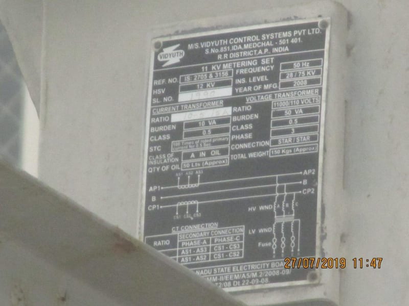
Utility side CTPT unit nameplate.

11_KV_CTPT_-_Edison_eqqani.jpg


Given that is 0.5 class, the no-load KVA demand (and no-load PF) is a bit suspect?

Muthu
 
Given that trafo no-load current is constant, wouldn't a colder winding with lower resistance have lower copper loss?
In one instance we found that the current through several small (about 1 KVA) transformers increased when the transformer was cold.
We did not try to separate the current into copper losses and eddy current losses.
That was beyond the scope of the course.

Bill
--------------------
"Why not the best?"
Jimmy Carter
 
Status
Not open for further replies.

Part and Inventory Search

Sponsor