Continue to Site

Eng-Tips is the largest engineering community on the Internet

Intelligent Work Forums for Engineering Professionals

  • Congratulations KootK on being selected by the Eng-Tips community for having the most helpful posts in the forums last week. Way to Go!

Maximum gap between two flat parts 5

Status
Not open for further replies.

Mako112

Mechanical
Jul 6, 2022
2
Hi all,

I need to control for the maximum possible gap between two flat parts. Is adding the two flatness tolerances a reasonable way of doing this? Say one part has a flatness tolerance of .003 and the other has a flatness of .002. Is the max gap between them .005?
 
Replies continue below

Recommended for you

Yes, you are correct. This would be the way to determine the maximum gap between two mating flat faces.
 
Oh that is annoying. I have to achieve very tight clearances measured with a feeler gauge. But one of the two parts is made with tempered glass and it is hard to reach the flatness that we need.

Thanks for the answer!
 
What is the reason for the small clearance? There are plenty of gap-filling materials for various functions.
 
Mako112,

While I would agree that this is a reasonable way to assure the gap between two nominally flat parts that mate up to one another, as with most things there are some caveats. If both surfaces are convex, there is the potential for rocking and deviation which may allow gaps larger than expected by simply adding the two tolerances.

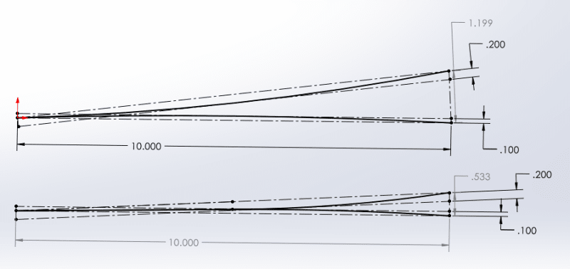
See the figure at the bottom of my post. The top is the absolute extreme theoretical worst case where the two parts are a pair of perfectly convex arcs which take up the entire tolerance zone, and touch only at their outermost points (rocked all the way to the edge). This probably isn't a realistic case, since for two reasonably large/heavy parts assembled in a direction where gravity is perpendicular to their surfaces this won't happen - but it could theoretically result in a gap ~8x the average of the two flatness tolerance zones and ~4x larger than the gap expected by adding the tolerance zones together. A slightly more realistic "worst" case is the bottom shown below, where the parts are in contact (and flat) across half their width and have some convex error through the other half which takes up the full tolerance zone - in this case we have theoretically a gap ~3.5x the average of the two flatness tolerance zones and ~1.8x larger than the gap expected by adding the tolerance zones together. (obviously I have changed the tolerance zone to allow for easier visualization. the same applies on a smaller scale).

While this is just theoretical, and reality may not even reach anywhere near even the second case especially if the supplier uses statistical process controls to keep the variation well within limits - it is worth knowing to either provide a slight buffer with tighter tolerances, or at the very least continuing your feeler gauge checks. It may be as simple as flipping one of the sheets if they are found to rock and/or fail the feeler gauge check.

Flatness_fxgg6k.png
 
problem lies is we have no idea what is the configuration of parts the OP is concerned with and what the fit form or function is.
is it for a seal with a gasket, or is it to maintain parallelism , or is it to hold parts perpendicular, and more, the different types of configurations
each have different challenged how they are machined. turned, milled, casting, ground, eg od grind, surface grind etc.
 
This is a sticky problem when Flatness is our only tool for control.

Flatness assumes infinitely rigid parts and that size/presence of a gap is equally unacceptable everywhere. In reality these are rarely both true. Declaring zones and adding clarifying notes can save great cost and time.

Is there any reason you can't specify your feeler-gage criteria on the part drawing?
 
I have to restrict/clarify my previous comment in which I confirmed that the sum of flatness tolerances is a reasonable way to evaluate the maximum gap, and say that it is true when the two faces are the main interface between the parts, meaning it is where the greatest mounting forces act and it is what orients the parts relative to each other. Speaking in dimensioning and tolerancing terms, it is when these surfaces are most likely to be selected as the primary datum feature for geometric tolerances on each respective part, constraining 2 rotational degrees of freedom, and have a flatness tolerance controlling their form. This is what I think the most relevant case for the OP's question is, so my answer is intact. But if from some reason the flatness tolerances are applied to surfaces that do not mate as the primary interface and there is more prominent constraint in the assembly - it is a different story and the gap might increase by the effect of the orientation errors between these faces and the primary mating faces. But that would be a rare and questionable application of flatness tolerances to begin with.

As for the rocking issue that was brought up by chez311 - usually, primary interface surfaces are clamped together by fasteners located more or less symmetrically to the center of the contact area. In such case, the mechanics of the process should balance the surfaces to the condition of minimum separation, and I believe the sum of the flatness errors is a good estimate for the said minimum separation gap. On a small part, even a single fastener designed to act at the center of the contact areas should do. This should make the effect of rocking on the functional assembly insignificant. I think rocking is more a free-state inspection issue for which there are the known ASME Y14 supported solutions such as the "single solution", "candidate datum set", etc.

Speaking of free-state, there is also the rigidity issue brought up in the last post here. Inspecting the parts for flatness in the free state and deriving from that the maximum gap expected, is actually the stringent (worst case) evaluation, when considering the expected effect of flexibility of the parts and the actual clamping forces at functional assembly. The actual gap can only become smaller than what the sum of flatness tolerances gives.
 
Burunduk,

Only the first case was really rocking, and definitely over conservative as I noted. The second case was in a stable position, with a gap to illustrate the point that the maximum gap calculated by adding the two flatness tolerance zones assumes that the tolerance zones would always be parallel and coincident which doesn't have to be the case. I still noted that this is also likely over conservative.

usually, primary interface surfaces are clamped together by fasteners located more or less symmetrically to the center of the contact area

OP did not specify. I imagined some sort of bonding or laminating procedure - not every assembly uses fasteners.
 
chez311,
I agree about the second case. Good observation.
 
Status
Not open for further replies.

Part and Inventory Search

Sponsor