Continue to Site

Eng-Tips is the largest engineering community on the Internet

Intelligent Work Forums for Engineering Professionals

  • Congratulations KootK on being selected by the Eng-Tips community for having the most helpful posts in the forums last week. Way to Go!

Maximum shim size under the 250 KW motor

Status
Not open for further replies.

rifa92

Mechanical
Apr 17, 2020
30
Hello Everyone,

We have a 250 kW motor that drives a boiler FD fan. Due to damage to the original motor, we are planning to install a replacement motor of the same rating. However, the new motor has a height difference of 40 mm from the motor foot to the shaft center compared to the original motor.

Could you please advise if any API standards permit the use of a 40 mm plate or two 20 mm plates under each foot of the motor? Additionally, could you provide guidance on how this modification might affect vibration levels?
 
Replies continue below

Recommended for you

You need to look at the vendor instructions.

For something that big I would be looking to modify the base plate with a large plate with a drilled hole or similar to raise the height of the base plate connection and maybe weld that plate to the base plate.

Got any drawings / sketch or photos?

Don't think API or similar will say yes or no.

You want to avoid any bending of the foot so anyhting you do needs to evenly spread the holding down force over the entire motor foot.

Remember - More details = better answers
Also: If you get a response it's polite to respond to it.
 
IMG_7621_m2heaw.jpg

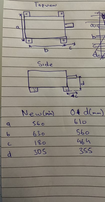
Thank you for response. I have attached a small sketch hope it helps. The new motor is to be installed in place of old motor. I’m thinking of using flat plate that covers entire foot area, drill through holes in the plate and bolt it with motor foot using hold down bolts.
 
Note that your sketcs shows the Vertical (d) dimension difference to be 50 mm. That is quite a difference for motor of same HP and Frame Size!

Thick plates, if machined flat, should not affect vibrations if soft-foot and shaft alignmnet are good. Allow 1 to 2 mm of height for thin SS shims to adjust vertical elevation to get precise vertical offset and angle toleraces for shaft alignmnet after correcting for soft-foot. Adjust the height of horizontal and axial Jacking Screws, as needed.

Walt
 
Sorry it was a writing error, it’s 315 not 305 mm. Secondly, motor power rating is same but frame size is different.

Would it be okay, if I use a machined flat plate but don’t weld it with bed and only hold it down with the bolts? Or should I weld it?
 
Welding is better then it won't move / slide or vibrate, but As its really just a big spacer bolting won't be too bad either.

better than a shim or block that big whatever happens.

Remember - More details = better answers
Also: If you get a response it's polite to respond to it.
 
Suggest at least tack-welding the thick plate to bed/foundation. Leave the thin shims loose or install tapered pins (with top nuts) from machine feet into thick plate to reduce shifting shaft alignment.

Walt
 
If you go the route of a big flat plate you first need to mount that plate to the foundation so that it's (ideally) level, and doesn't have a "soft corner".

Then you need to mount the new motor to the plate so it's aligned with the load and doesn't have a soft foot.

I can't read your C dimension for the old motor. Are you going to have a big overhang of the new plate?

 
This is also in the ideal thickness range for epoxy chocking compounds. Your footprint is small so you may have to adjust bolt tension accordingly.
 
is there any reason why the baseplate can't be removed and spacer pads welded onto the existing positions, redrilled and the whole baseplate machined?

It is a capital mistake to theorise before one has data. Insensibly one begins to twist facts to suit theories, instead of theories to suit facts. (Sherlock Holmes - A Scandal in Bohemia.)
 
Thank you for all the responses. Ideally, I don't want to weld as we will be overhauling the old motor and put it back when this new motor requires repair etc.

We want to make a universal bed on which I can fit both types of motor (low cost) instead of buying a brand new motor of same specs.
 
Normally, the choice is to manufacture a nearly-full-height spacer plate which covers both teh old footprint and the new. The plate is milled flat (both sides) so it lays flat against the existing bedplate and flat against the new motor foot. The motor side of the plate is counterbored so that you can bolt it down (preferably in the old holes, but going by your geometry this may not be possible). The new motor foot get bolted into tapped holes in the plate.

If you're REALLY lucky, a pair of the foot bolt locations will line up exactly, and you can run a single bolt all the way through. Depending on how the original was mounted, that may be a stud coming up from the concrete foundation through the old motor foot - and may thus not be long enough to also go through the new spacer.

Looking at the given dimensions - does the foundation actually run from the old motor foot right up to the end of the shaft? And is it at least 200 mm wider (from the old foot bolt location toward the centerline)? If the old motor really needed the 464 mm from end-of-shaft to hold-down bolt, the new one doesn't appear to have anywhere near enough coupling fit length.

This is because the new motor foot bolts are going to be 35 mm closer to the centerline (horizontally). The new front one will be 285 mm closer to the load, and the new back one will be 215 mm closer to the load (compared to the corresponding old bolts).

Converting energy to motion for more than half a century
 
Status
Not open for further replies.

Part and Inventory Search

Sponsor