Eng-Tips is the largest engineering community on the Internet

Intelligent Work Forums for Engineering Professionals

  • Congratulations waross on being selected by the Tek-Tips community for having the most helpful posts in the forums last week. Way to Go!

MCSF limits for VFD centrifugal application? 5

Status
Not open for further replies.

bentov

Electrical
Feb 2, 2004
74
0
0
US
A customer's new pump (Berkeley B3ZPM) will be supplied by a 900ft 4" PVC underground pipe fed by a water district turnout with a "normal operating range" of 17.5-20psi. The pump supplies water trucks (12ft high) and a fire water tank (16ft high) through a back flow preventer (10psi pressure drop) and fill valves. My plan is to control it with a VFD in PID via suction inlet pressure (NPSHa rises, pump speeds up, slows down when it drops, sleeps & wakes on thresholds, field tuning for min/max hz limits), with a simple pressure differential switch on the discharge side to provide a run command. The idea is to extract maximum available volume from the unpredictable inlet conditions while avoiding cavitation.

If I'm doing the math right, max pipeline flow would be 300gpm based on friction loss at 20psi (46hd-ft). Available flow ranges to supply the booster pump (given 20-17.5psi = 46-40hd-ft) are something like: 200gpm@ 24.4-18.4 NPSHa, 225@ 19.1-13.1, 250@ 13.3-7.3, 275@ 7.0-1.0

With the BFP, other friction losses plus static lift, the operating points for the pump range from 25 to around 45hd-ft. When I experiment with impeller diameters using the (very cool) Pentair BEC2 Electronic Catalog tool, full diameter (9") provides wonderfully low NPSHr at the desired flow rates (example: 1290rpm 266gpm@45' = 6.9' NPSHr), but the lower head (1000rpm 272gpm@25ft/5.3 NPSHr) falls on the "Full reject" MCSF curve shown.

When impeller diameter is reduced to 7.63" to avoid MCSF: 1557rpm 365gpm@45'/16.5' NPSHr, 1220rpm 280@25'/11.1' NPSHr
Seems like a lot of volume to lose (because NPSHa will be inadequate for those rates at this diameter, VFD in PID will sleep) . . .

My question then: how risky is it to ignore MCSF for portions (initial fill) of expected operating time?
 
Replies continue below

Recommended for you

Some pictures and curves would be good here. You don't have unpredictable inlet conditions, you seem to have varying outlet conditions.

I think you could do all of this with a fixed speed pump and a control valve controlled in part by inlet pressure.

Be aware that NPSHR doesn't mean you won't get cavitation of the pump.

Normal practice is to allow a1-2m (4-6ft head above NPSHA to provide this comfort level.

But in answer to your question the clue is in the C part of MCSF - continuous. Now how this is defined is often rather wooly or simply not stated.

SO it could be 30 mins, 6 hours, one day - No one really knows. What time scale are you looking at to operate below this magic curve line ( which is actually a thick fuzzy line).

Remember - More details = better answers
Also: If you get a response it's polite to respond to it.
 
I agree with LittleInch's suggestion of using a constant speed pump.
See this thread that I just answered for typical use guidelines for VFD. thread407-484994

Your head requirements are basically constant and your demand should really be filled by the highest flow rate possible while maintaining NPSH. You should be able to set that by fixing only one safe minimum suction pressure, as the filling rate of trucks is not exactly a critical application that requires VFD flow control. Any reasonable flow rate is OK. Its something determined by suction pressure, with or without VFD. You apparently need suction pressure control.

Suction pressure control for NPSH by VFD is difficult and probably not necessary. You only have a few psi to use as your control signal. And really, you are interested in only one value, NPSHR. One value pressure control of NPSH boils down to On/Off. You can pump when you have it and don't pump when you don't. You could easily do this with a pressure switch to cut power to pump on low suction pressure. Realistically, I dont know why you would even need a control valve. With min NPSHR covered by PSL, excess NPSHA provides its own flow control.

A PSL is not as kool as a VFD, but it is far more efficient.

 
Hello, thanks for the replies. I have a sketch I'll try to scan and upload to clarify. We are going to try this with the full diameter impeller, will see what happens at the low speed where MCSF is indicated, maybe set a minimum to tune out any problems.

There's a typo in my post, "7.63 inch to avoid MCSF: 1557rpm 365gpm@45'/16.5' NPSHr" (should say 265gpm, not 365). I was trying to emphasize the dramatic difference in NPSHr for identical flow and head points at the respective impeller diameters (16.5' at 7.63 vs. 6.9' at 9.0).

I did consider a flow control valve (200gpm) and just an inlet side pressure switch. At 1750rpm 9", 200gpm is 87' (so 42' of throttling required at our 45' operating point). NPSHr is not shown at that point on the curve (leaves off to the right at 270gpm, 11' - appears flat though, not dropping even if I hand draw an extension) - takes 7.2hp. Given ample NPSHa a standard 1750rpm selection would be 7", 200gpm @ 48', NPSHr = 25', 3.6hp. It does seem magical that using the 9" with a VFD, we can get 200gpm at 40+ ' at 1225rpm, NPSHr = 5.8, 2.6hp.

Truck filling is a big deal, takes 30 minutes or more now (2000 gallons, so "push" from pipeline through BFP amounts to around 67gpm). It appears we can pull 266gpm (7.5 minute fill) with the 9" impeller at 45' & 6.9' NPSHr (vs. the roughly 10' NPSHa at that flow rate). Everything 1750rpm, whether or not flow is restricted, appears to require more suction head for similar volume. I frequently "unsell" VFDs, but seems like the answer here.

It will be interesting to see how well the PID loop works (do it all the time for discharge pressure, 1st attempt here controlling for suction). I'm hoping it will be smooth, take maximum advantage of available water supply . . .
 
Nothing there changed my opinion.

If your problem is suction pressure and NPSH, no VFD will cure that.

If fast truck loading is the problem, you need to do that at the max rate. It will never be more than what your suction pressure will supply. A VFD will not change maximum rate.

The ONLY thing a VFD will let you do is pump a wide variation of flow rates efficiently. If money is the problem, get a vfd. You will be able to pump low flow rates, <60% BEP, cheaply. Higher flows will cost about the same.

I suggest your money is better spent on curing your suction pressure troubles.

Build a tank. Fill it at whatever maximum rate that supply pressure allows. When a truck comes, turn on a high speed, high capacity pump and fill the truck in 60 seconds or whatever. Like Formula 1. (They gravity fill, no pump needed). Do that until the tank runs dry, or no more trucks come.

I think you just want to play with a VFD toy.

 
What would be more useful than a sketch is an estimate of the times in h:m that you will operate the pump at various flow rates on a typical operating day (when not limited by suction pressure) and a system curve.

If you can't estimate that, you should probably not be thinking about vfd.

Since neither vfd or cv will cure suction pressure issues, you should also have an estimate of typical suction pressures and their h:m per day. As you can only have a valid solution of any kind for times when suction pressure is above minimum.
 
Thanks again for the replies, sorry for responding late here.

I do like playing with my VFD toys. This part still seems magical to me: "1750rpm selection would be 7", 200gpm @ 48', NPSHr = 25', 3.6hp . . . using the 9" with a VFD, we can get 200gpm at 40+ ' at 1225rpm, NPSHr = 5.8, 2.6hp"

Our system here ("900ft 4" PVC underground pipe fed by a water district turnout with a "normal operating range" of 17.5-20psi") is unpredictable, that "normal range" is all over the map at different times (often way below normal), beyond anyone's control. A friend of mine makes fun of me for misunderstanding NPSHr & NPSHa, says they must be corrected for atmospheric (so 25' is really 25-14.7= 10.3', 4.5psi if monitored by gauge), says for testing they use a vacuum gauge at pump inlets to find problems. I definitely need to understand that part better - seems unfair that NPSH must be corrected, but NOT the standard flow/head output curve - but for now I'll take his word for it.

Any case, we set this one up as described, but used a 7" instead of 9" impeller (cause already built that way), found we could overspeed the pump without overloading the motor and with no evidence of cavitation (on the day of the test, at least) - filled up trucks in 5-6 minutes, everybody happy. The discharge side pressure switch is set for On at around 15, Off around 25 psi, seemed to cycle well (no oscillating/short cycling). I set the PID loop at 5psi, reverse action (so VFD runs full blast, then slows down/sleeps when inlet pressure drops) - didn't get to test that part as they installed no local valve on the supply side, said they would test it later by throttling the supply line valve at the other end.

All in all I think it's a reasonable design, providing automatic response to highly variable NPSHa while seeking maximum flow rate without pump damage or tripping. We did consider the gravity storage tank, also worried a hydrotank might be needed on the discharge side - seemed cheaper/easier to just try the VFD first. I wanted to understand the 9" impeller thing (so then our VFD current limit/speed foldback would kick in below, rather than above nominal 60hz), might do that later if they do have problems with poor supply pressure. Meantime it seems to work OK.
 
How much of the 900' of line is yours?
Putting the pump closer to the source will greatly improve the NPSH situation.
Much easier to push water than suck it.

= = = = = = = = = = = = = = = = = = = =
P.E. Metallurgy, consulting work welcomed
 
I'll make fun of both you and friend. You correct for NPSHa by adding atmospheric pressure.
NPSHR is given in "absolute ft" or when converted to pressure, it is absolute pressure.
"(so 25' is really 25-14.7= 10.3', 4.5psi, if monitored by gauge"
You cannot subtract psi from feet. Convert the psi to feet and then you can.
If it is psi, rather than 25', you add 25psi to 14.7 psi =40psi, that's 92.3 feet of water.

NPSHA is calculated by summing the following

+Ft of Head equivalent of applied pressure, if drawing from a pressurized tank or pipeline)
+Ft of elevation (+ is elevation of suction water surface above centerline of pump)
..... If drawing from a pressurized pipeline, use pipe centerline elevation,
..... by converting gage pressure from gage elevation to pipe centerline, or
..... simply use the elevation of the gage.
-Ft of Friction loss in suction pipe, valves, fittings and tank exit coefficients
-Ft Head equivalent of vapor pressure
+Velocity head (often ignored)


Keith, Others
Please notice the correction in the edited post above. "If drawing from a pressured pipeline, use the indicated pressure with the gage's elevation by converting indicated pressure to pipe centerline elevation, or simply use gage's elevation."

---------- Revised Text------------
NPSHA is calculated by summing the following

+Ft of Head equivalent of applied pressure, if drawing from a pressurized tank or pipeline)
+Ft of elevation (+ is elevation of suction water surface above centerline of pump)
..... If drawing from a pressurized pipeline, use pipe centerline elevation,
..... by converting gage pressure from gage elevation to pipe centerline, or
..... simply use the elevation of the gage.
-Ft of Friction loss in suction pipe, valves, fittings and tank exit coefficients
-Ft Head equivalent of vapor pressure
+Velocity head (often ignored)
-------------------------------------

And be sure that friction loss in the suction line is calculated using the gage to pump length of pipe starting from the point where the gage connects to the pipeline.
 
Bentov, Ed Stainless asked a good question that is still unanswered - re pipeline owernership. Locating the pump towards the town main supply overcomes many problems but of course doesn't help you getting your kick out of using VFD.

It is a capital mistake to theorise before one has data. Insensibly one begins to twist facts to suit theories, instead of theories to suit facts. (Sherlock Holmes - A Scandal in Bohemia.)
 
If the NPSHA is calculated correctly, there could be no problem. NPSHA is apparently around 25ft (dependent on height of the gage).

With a only a 900ft run, its going to take a long distance to recover head lost to friction. Its probably cheaper to increase the pipe diameter, maybe for only the first half of the run, than to drag the pump station and power cables off the plot plan to perhaps some location 400ft down the street.


Prior to going any further with how do I overcome my problem, the very first question to be answered is, do the local authorities allow direct pumping from their main?

My experience is, no they don't.

It is a capital mistake to theorise before one has data. Insensibly one begins to twist facts to suit theories, instead of theories to suit facts. (Sherlock Holmes - A Scandal in Bohemia.)
 
Some Plumbing Codes require that all booster pumps be equipped with a low-pressure cutoff switch, which prevents the creation of a vacuum when the pressure on the suction side reaches values of 10 psi or less. When negative pressure isn’t accounted for, a phenomenon called cavitation occurs, where small bubbles rapidly form and collapse in the flowing water. Cavitation can cause localized shockwaves, damaging the booster pump impeller and inducing mechanical vibrations, which affect the motor driving the pump as well.

bentov (Electrical)(OP) said:
Our system here ("900ft 4" PVC underground pipe fed by a water district turnout with a "normal operating range" of 17.5-20psi") is unpredictable, that "normal range" is all over the map at different times (often way below normal), beyond anyone's control. A friend of mine makes fun of me for misunderstanding NPSHr & NPSHa, says they must be corrected for atmospheric (so 25' is really 25-14.7= 10.3', 4.5psi if monitored by gauge), says for testing they use a vacuum gauge at pump inlets to find problems. I definitely need to understand that part better - seems unfair that NPSH must be corrected, but NOT the standard flow/head output curve - but for now I'll take his word for it.

Atmospheric pressure is added to the NPSHa when you have an open tank, but is not added to the pressure from a pressurized pipeline.

Per your stated pressures, you don't have adequate NPSHa to make this system work. With a flow of 300 gpm, you have 17.5 psi pipeline headloss. That would leave you with 0 - 2.5 psi NPSHa.

As others have stated, you need a bigger pipe diameter or relocation of the pump.

 
bimr: my experience is NO direct pumping from the main as it can lead to putting the main under vacuum (vacuum breakers can fail).
The quick cals. I did, probably 200GPM is not achievable.

Gravity storage tank at the discharge seems the best solution and could even negate the need for a pump - not unlike refilling the water tanks in the railway steams engines of years ago.

It is a capital mistake to theorise before one has data. Insensibly one begins to twist facts to suit theories, instead of theories to suit facts. (Sherlock Holmes - A Scandal in Bohemia.)
 
There is no difference between the calculation for a closed pressurized tank, or a closed pressurized pipeline.

NPSHa calculation is the same for all. The same for an open or a closed tank, or a pressurized pipeline. The object being to obtain total head, which always includes atmospheric pressure. As gage pressures do not ever include Patm, whenever you have a gage pressure, be it from a gage placed on a pipeline, or on a tank, it needs to be added.

This link has several examples of the NPSHA calculation, showing both that for open and closed tanks. Note that the pressure given for the closed tank example is already in units of PSIA, so Patm has already been added to the tank's gage pressure reading.

There is no difference at all between the calculation for any open, or closed pressurized tank, or a closed pressurized pipeline.

What follows however is somewhat different between tanks and pipelines.

Including Velocity Head
If you include velocity head, rather than ignore it, you must use the velocity at the point where the pressure reading is taken. If the gage is on a tank, the velocity in the tank is probably zero, or very close to zero, as a tank's area of flow is usually very large and velocities within very, very small. If the gage is on a pipeline, the velocity will probably be small, but not zero and, if there is a velocity, the pressure gage will not include any velocity head in its reading of static pressure head alone, therefore you can add the velocity head at that point where the gage is attached, if you want to account for velocities heads. It is conservative to ignore it and they usually don't amount to much anyway.

Note: Following reference specifically says P[sub]suction[/sub] = "stagnation pressure"
Stagnation pressure includes any velocity head

There is no difference at all between the calculation for any open, or closed pressurized tank, or a closed pressurized pipeline.even when including Velocity head, but you must remember to use the velocity at the pressure gage's location, whenever you choose to include velocity head.

Lastly

The acceleration head of a reciprocating pump is another potential loss, which must be subtracted from NPSHA, but only if a recip pump is used.
 
Not forgetting 10 psi pressure drop back flow eliminater + plus fill valves etc.

Requires a thorough hydraulic calc to establish the facts.

It is a capital mistake to theorise before one has data. Insensibly one begins to twist facts to suit theories, instead of theories to suit facts. (Sherlock Holmes - A Scandal in Bohemia.)
 
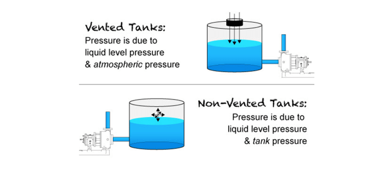
Atmospheric pressure is not added unless the tank is open to the atmosphere:

Picture1z1_uzjlrj.png


In the OP post, the system is not open to the atmosphere.

Artisi, I don't understand your comment regarding booster pumps. Every high-rise, hotel, stadium as well as many commercial and industrial facilities use direct connected booster pumps. Putting tanks on building rooftops is no longer done. Would expect the connection to have a backflow preventer as well.

Link

Here it is mentioned in the building code.

"Per the IBC, a low pressure cutoff was and still is required on all booster systems to prevent negative pressure on the suction side of the pump when a positive pressure of 10 psi or less occurs on that side. Before the days of building automation system connections, alarms consisting of a light or horn would alert the building engineer on-site to any issues requiring attention."

Link
 
Status
Not open for further replies.
Back
Top