Continue to Site

Eng-Tips is the largest engineering community on the Internet

Intelligent Work Forums for Engineering Professionals

  • Congratulations GregLocock on being selected by the Eng-Tips community for having the most helpful posts in the forums last week. Way to Go!

MCSF limits for VFD centrifugal application? 5

Status
Not open for further replies.

bentov

Electrical
Feb 2, 2004
74
A customer's new pump (Berkeley B3ZPM) will be supplied by a 900ft 4" PVC underground pipe fed by a water district turnout with a "normal operating range" of 17.5-20psi. The pump supplies water trucks (12ft high) and a fire water tank (16ft high) through a back flow preventer (10psi pressure drop) and fill valves. My plan is to control it with a VFD in PID via suction inlet pressure (NPSHa rises, pump speeds up, slows down when it drops, sleeps & wakes on thresholds, field tuning for min/max hz limits), with a simple pressure differential switch on the discharge side to provide a run command. The idea is to extract maximum available volume from the unpredictable inlet conditions while avoiding cavitation.

If I'm doing the math right, max pipeline flow would be 300gpm based on friction loss at 20psi (46hd-ft). Available flow ranges to supply the booster pump (given 20-17.5psi = 46-40hd-ft) are something like: 200gpm@ 24.4-18.4 NPSHa, 225@ 19.1-13.1, 250@ 13.3-7.3, 275@ 7.0-1.0

With the BFP, other friction losses plus static lift, the operating points for the pump range from 25 to around 45hd-ft. When I experiment with impeller diameters using the (very cool) Pentair BEC2 Electronic Catalog tool, full diameter (9") provides wonderfully low NPSHr at the desired flow rates (example: 1290rpm 266gpm@45' = 6.9' NPSHr), but the lower head (1000rpm 272gpm@25ft/5.3 NPSHr) falls on the "Full reject" MCSF curve shown.

When impeller diameter is reduced to 7.63" to avoid MCSF: 1557rpm 365gpm@45'/16.5' NPSHr, 1220rpm 280@25'/11.1' NPSHr
Seems like a lot of volume to lose (because NPSHa will be inadequate for those rates at this diameter, VFD in PID will sleep) . . .

My question then: how risky is it to ignore MCSF for portions (initial fill) of expected operating time?
 
Replies continue below

Recommended for you

bimr; my only comment re booster pump was it may not be needed, as usual we are not privy to the overall scheme of things - maybe the fill point is out in the never never - how many times a day is the tanker or fire pump filled and at what rate of fill.

The next thing we will be asked is because the deliver head will be 12ft or 16ft - why does my pump keep tripping out on overload - maybe because its capable of 40 or 50 ft and its operating way right on its curve.

my comment on gravity tank was based on the high head loss thru the 900 ft line etc at the rate of fill nominated - if little water is required per hour / day etc, a header tank will more than likely be the best move - it has time to constantly fill direct from the pipe line -

But, we are crystal ball gazing at the moment - nothing unusual .

Nearly enough for me this year on this one - lets see if we understand more next year.


It is a capital mistake to theorise before one has data. Insensibly one begins to twist facts to suit theories, instead of theories to suit facts. (Sherlock Holmes - A Scandal in Bohemia.)
 
Bimr.

NPSH is always measured in absolute terms as head of liquid.

Your claim only works if the pressure measured in the pipe is expressed in absolute pressure units, bara or psia. Most guages and transmitters provide pressure relative to local atmospheric pressure, bar(g) or psi(g). Then you need to add local atmospheric pressure to gauge pressure when you do NPSH calculations to get absolute pressure.

Remember - More details = better answers
Also: If you get a response it's polite to respond to it.
 
LI,

Of course, you are referring to the a in psia means that the pressure is measured above absolute zero, a perfect vacuum.
 
An absolute vacuum. What better reference point is there. Same one the atmosphere uses.

 
Bentov,

It would be useful if you could supply the following information:

1) Is your back flow preventer before (suction side) or after (discharge side) of your pump
2) Is there any elevation change from your tapping point on the main to the pump?
3) what is you calculate or measured pressure drop at 200 and 300 gpm?

You seem not to have grasped that NPSH is measure din absolute terms, so feet above an absolute vacuum. SO a gauge reading of say 5psi (11.55 ft) in absolute terms is actually 5 psi + local atmospheric pressure (14.5 at sea level), so 19.5 psia or 45 feet to compare to your NPSH figure.

HOWEVER, the points made above by others are valid. If you are transporting potable water, you really don't want to go below 0psi(g) or really less than 5 psi. Apart from any regulations that the water company has, this leaves open the potential to allow unfiltered ground water into your pipe which would contaminate your supply.

Therefore your best bet if this is the case is to set your PID controller to 5sig at the pump inlet and maximise flow based on that.

Very few pumps of this size have an NPSH higher than 25 ft and most much less, so any pressure above 0 psig at the inlet will be good enough.

Remember - More details = better answers
Also: If you get a response it's polite to respond to it.
 
If you are attempting to set up a system like this you need to understand the principles of cross connection control and booster pump systems. This a a good reference EPA Cross-Connection Control Manual - also attached.

Your pump must be controlled so it will not operate when the pump suction pressure is less than your jurisdiction's criteria. With the pipe size, length, flow rate, and the initial pressure range provided I suspect that most of the time the pump would short cycle, as the low pressure switch would turn the pump off as soon as it is started.

This makes the entire question about NPSH moot, as your pump suction is not allowed to be below the criteria pressure for this pump.

You will need either an airgap at the truck fill point (there are rules about air gaps) or another type of cross connection control device, appropriate for your piping arrangement. The installation may be subject to codes compliance AHJ plans review / approval, you should check.
 
 https://files.engineering.com/getfile.aspx?folder=517cfd59-2281-40fd-85d3-c2bcff8cb34c&file=epa816r03002_0.pdf
Well this got busy, been away, sorry . . . this thread was kind of inactive, just noticed while checking for replies to my other one (hoping for a rule of thumb on downthrust k factor, no luck there yet) that I left it hanging, felt guilty so followed up (while sleepy, short on time). For the record, I do know the difference between hd-ft & psi (and my pump buddy certainly does), but I deserve to be made fun of for my brain fart.

Some answers: the "jurisdiction" is a closed irrigation district pipeline supplying non-potable water to farmers; the backflow device is after the new pump; the water truck and firewater tank fills are air gapped; there is no elevation change between tap and pump; calculated pressure drop at 200gpm = 21.6ft (5.11fps), at 300gpm = 46ft (7.7fps)

44, thanks for all the input. I read those links (had seen Evans before but not Henshaw and the "desire" of fluids to boil). It's comforting to recall how widely misunderstood are NPSH and cavitation, and that I'm not the only one.

To rephrase the dumb part, my friend made fun of me for not knowing to add atmospheric to the NPSHA (so at sea level we start with 14.7x2.31= 34ft). So to monitor the suction inlet for inadequate NPSHA on that pump with psig (gauge, corrected for atmosphere) vs psia (absolute) devices you'd need to calibrate for 25-34 = -9ft (or -3.9psi) - thus a vacuum (rather than pressure) gauge or transducer. As I recall he said "no problem, you'll be plenty safe at 5psi" while shaking his head at my ignorance.

To be clear: NPSH (Required and Available) in pump specs is always expressed in absolute, yes? In our closed pipeline, the NPSHA at the pump inlet will be whatever is leftover after the pipeline friction loss? I used the applied pressure stated by the supplier, 20psi (46ft), subtracted the 21.6ft friction losses at 200gpm, leaving (46-21.6=) 24.4ft NPSHA for the pump. Was I supposed to add 34ft at the beginning, so then it's 46+34= 80ft applied, 80-21.6= 58.4ft NPSHA at the pump inlet? That seems way too high (since by all accounts this system is in trouble due to inadequate supply), must be missing something still . . . getting sleepy again, go ahead and make fun of me, I can take it.
 
I have found that anytime you do hydraulics it is more convenient to always work with absolute pressure. Convert EVERY pressure you have TO ABSOLUTE pressure ... immediately.

NPSHr is given in ABS head.

Supplied pressure is usually given in gage pressure, but obviously there is no standard convention. When any given pressures are not specified as psiG, or psiA to be either gage or absolute, I assume gage pressure for preliminary work, but VERIFY that it is gage. It is also good practice to verify the msl elevation of the pump installation site, because they are not always going to be at sea level with 14.7 psia atmospheric pressure (33.9ft) and 60°F. I subtract 0.5 psi (and maybe) 3°F for each 1000ft above sea level, although using the highest site temperature is usually more conservative.

20psiG + 14.7 psi = 34.7 psiA
34.7 psiA × 144/62.37 = 80.1ft
Friction loss Hf = 21.6ft
Friction loss 21.6ft x 62.37/144 = 9.4 psi
Head at suction 80.1ft -21.6ft = 59.5ft
Suction Pressure 59.5ft x 62.37/144 = 25.8 psiA -14.7psi = 11.1 psiG
You mentioned that low pressure supply is 17.5 psiG, so min suction pressure might be 2.5 psi less
MIN Suction Pressure = 11.1-2.5 = 8.6 psiG (23.3 psiA)
MIN Suction Head = 23.3 psiA x 144/62.37 = 53.8 ft

Since vapor pressure is very small and supply pressures of 17.5 to 20psi? (the pipeline pressures are gage pressures, right?), then it looks like lots of suction head is available. 20 psiG, even 900ft away is quite a lot of head. If the typical house had a 6" pipe connection to the mains, we would all have a good sense of how much head that really is, but we'd get too beat up and battered around in the shower. What we usually see is the few psiG available at the end of a 25ft x 1/2" garden hose. If I can get 20 psiG pressure at the inlet to a large pump station, that's usually more than what I need to keep all the monsters well feed.

Pierreick (Chemical)3 Jan 22 06:48 2nd reference is great. Its very complete with lots of additional references included in one pdf that will save much hunting around for all the other stuff you usually need to do pump system design.
 
That's ok - it took 6 months last time ;-)

So your questions

NPSH (Required and Available) in pump specs is always expressed in absolute, yes? YES

In our closed pipeline, the NPSHA at the pump inlet will be whatever is leftover after the pipeline friction loss? - More or less. Is your pipeline truly horizontal? - Not even a few feet going from underground to the pump inlet? Whilst it is fairly small, don't forget vapour pressure of the water - ~1ft at 20C, but can get significant at higher temps.

I used the applied pressure stated by the supplier, 20psi (46ft), subtracted the 21.6ft friction losses at 200gpm, leaving (46-21.6=) 24.4ft NPSHA for the pump. [highlight #FCE94F]Was I supposed to add 34ft at the beginning,[/highlight] so then it's 46+34= 80ft applied, 80-21.6= 58.4ft NPSHA at the pump inlet? That seems way too high (since by all accounts this system is in trouble due to inadequate supply), must be missing something still - Yes.

SO other question - Is there anything in the line between the tap off point ( valves, bends, elbows, filters, connections with smaller ID etc)
Also what exactly is your pipe? Is 4" the ID or OD? even a few mm smaller ID makes a big difference at this level.

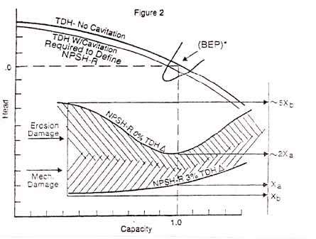
Also don't forget that NPSH is not onset of cavitation. The way they measure this is to slowly throttle the inlet until the head difference between inlet and outlet drops by 3% for the same flow rate. As shown in the graph below, you can get a divergence at higher flows between cavitation and NPSH. The usual action is to provide somewhere between 1 to 3m ( 4 to 10 ft) above the NPSH value to avoid cavitation.

Your value of NPPSHR at 25ft is quite high and indicated you are at a high speed with a small impellor.

NPSH_kdmptr.jpg


Remember - More details = better answers
Also: If you get a response it's polite to respond to it.
 
It's a "will be supplied by a 900ft 4" PVC underground pipe".
This calculator gives a 9.2 psi loss for 200gpm
BUT it also gives 19.6 psi loss for 300gpm


20psiG + 14.7 psi = 34.7 psiA
34.7 psiA × 144/62.37 = 80.1ft

Friction loss @ 300gpm 19.6psi x 144/62.37 = 45.25ft
Head at suction 80.1ft -45.25 = 34.8ft
Suction Pressure 34.8ft x 62.37/144 = 15.1 psiA -14.7psi = 0.4 psiG
You mentioned that low pressure supply is 17.5 psiG, so min suction pressure might be 2.5 psi less
MIN Suction Pressure = 0.4-2.5 = -2.1 psiG (12.6 psiA)
MIN Suction Head = 12.6 psiA x 144/62.37 = 29.1 ft
-Vapor Press/Head = est 0.82ft @ 70°F
NPSHa = 28.3ft
NPSHr = ?
 
Now back to the VFD to control flow problem.

A VFD should not be used as flow control based on suction pressure.
Supply pressure is natural flow control. As supply pressure increases, so does flow. As supply pressure decreases, so does flow. Furthermore, you cannot change the supply flow rate from a pipeline to be more, or less than what the supply delivers at any given supply pressure. What you do downstream does not change that. That's a bit different than pumping from a tank that will usually supply whatever you want until it runs out. Any change you make to the flow rate or pressure delivered by a pipeline should be considered extremely temporary, or you will probably begin to affect the pipeline's operation upstream, something that usually causes trouble.

So, IF YOU CANNOT CHANGE THE SUPPLY PIPELINE FLOW RATE & PRESSURES, as it is a property of the supply pipeline, how will adding a vfd help?

A vfd cannot make more water, nor can it eliminate water. It can only change the pressure of the flow it is given. If it can change the flow rate of the supply pipeline, then the vfd is either drawing down the pressure of the supply pipeline by taking more water than the pipeline can deliver, or slowing down the pipeline water delivery and increasing the pipeline pressure. This is the paradox of hydraulic analysis. You must begin your calculations at a point where the flowrate and pressure characteristics are very well known, and in fact, they must be constant, unless you are doing a dynamic analysis. Dynamic analysis still requires that constant flow and pressure be maintained somewhere in the system for the short period during each time step, however they are allowed to vary between time steps.

 
It does often feel like I'm battered by the need for some attempt at dynamic analysis despite not fully understanding the regular kind, oh well! Regarding use of VFDs for flow control based on suction pressure, I do have a local example. A canal company captures drainage water in large ditches (with highly variable flows) using large pumps that start to cavitate when the level is low. We supply VFDs with submersible level transmitters, setup PID so pumps slow down as level drops. The efficiency is horrible but they don't care, happy to capture the available water that was otherwise lost when pumps were turned off to avoid self destructing.

This case seemed similar, problem was unpredictability of the supply beyond our control. Without actually monitoring all conditions carefully, we can say that the "push" through the pipeline (based on known truck fill rates) was averaging 60-70gpm, which seemed about right given stated applied pressure and BFP loss plus calculated friction loss (seemed a little high actually, probably because I was leaving out atmospheric). Filling the (very large) yard dust control trucks was a constant irritant/inefficiency, but fighting a recent fire and seeing the storage tank nearly emptied while watching the pathetically slow refill rate really got some attention. The goal here is similar to the drainage capture: stepless pump speed response to available supply (whatever it happens to be) at maximum possible flow, automatic full time till tanks are full. While admitting my lack of qualification for proper hydraulic analysis, I offered to setup the VFD thing as an initial problem solving attempt (because it's cheap compared to other alternatives, and yes, kind of fun I guess).

When I first started talking about this with my pump friend (over beer, after I tried to give him the analysis job for pay, which right away sounded to him like more trouble than it was worth), his reaction was "it'll never work, need to put the pump at the other end, or make the pipeline a lot bigger, or at the very least install a vented storage tank at the pump". I sense that was the first impression on this forum as well, but now it seems there's consensus that we do have adequate NPSHA for at least 200gpm - maybe more, though I expect new problems arise (air entrainment?) at higher pipeline velocities. And yes LI, the high NPSHR is due to a small impeller at high speed, which brings me back to my original question (looking at forcing our pump to be a 1200rpm design with a 9" impeller using a VFD, taking advantage of the dramatic reduction in NPSHR for the same flow rate, but flirting with "full reject" on the MCSF curve).
 
This one's quite fun though.

I don't agree with my respected friend mr 44 - you can control any VFD on anything you want and inlet pressure is one parameter for sure to maximise flow. You can then set it not to go too fast if the inlet pressure rises more than you anticipate.

Basically though looking at some pump curves, your chosen pump is WAY TOO BIG. See page 46 for your pump.

You want something more like the pump on page 41 - where 300 gpm is closer to the right hand end of the curve. A large diameter slow running pump will give you better NPSHr. However once you go below 0psig other things might happen. If you've already got that pump then so long as you don't go below the MCSF for too long I wouldn't worry. These are not large pumps just bigger than you need. As you say efficiency falls off a cliff, but if it maxes out flowrate for a short while who's worried.

Your velocities are a bit higher than "normal" but you won't get any air entrainment off a pipeline supply unless you're got a lot of air then you might need to avoid going below 0 psig.

Oh and I keep reading BFP as Boiler Feed Pump and not Back Flow Preventer....


Remember - More details = better answers
Also: If you get a response it's polite to respond to it.
 
LI, I agree you can control it on suction pressure or flow, but why would you. This system is limited by available supply. You can never, never maximize flow to be greater than what the supply can give you, no matter how you control it. Please think of some scenario that might prove how you could do it. This problem is a good enough example. The object is to fill the trucks as fast as possible. Here I think the range we can pump from with a vfd or cs pump is 200gpm at 20psig to 300gpm at 17.5psig. Assume supply parameters are linear in between those two points. Control that, or any other parameter and it will not increase system flow. The best you can do is pump at max rate. A cs does that with no control, until it runs out of NPSH. That is a on/off low pressure suction switch. Don't need vfd to do that. What would be your maximum flow? How can you get more flow and stay within the supply limits. To fill a truck fast, run at max until suction drops, turn off, wait until suction returns, do again. With vfd, when suction drops, go to idle. That's the only difference. Otherwise run as fast as possible. Tthat may also mean you will always operate very close to min NPSHr. The cs will start, run a bit, then stop. The vfd will run constantly, but very slow or at idle when near lo P limit. Neither has appreciable advantage there, vfd will be more economic, if suction p returns slowly and it can spend a lot of time pumping at low rates. So is it better to run all day at low rates, or just shut off for awhile and wait until suction p builds higher and shoot it out quickly at constant speed, then shut down again. I dont know. More info required.

The only thing you can do with a pump, a vfd controlled pump, or a constant speed pump, is pump at some flow rate that is within the available supply rates. With a vfd pump you may be able to do that more efficiently when you want to pump at rates that are 30% less than the Constant Speed, CS, BEP rate, maybe not. The CS BEP - 30% is an approximate economic break even point for many VFD-CS decisions. Other of the economic advantage, you can do exactly the same thing with a CS pump and a control valve. Neither option will flow any more, or any less than the other. Neither option will increase pressure any more than the other.

The ONLY advantage of a VFD is efficiency in pumping at rates of 10 to 70% of CS flow. If you pump at very low rates a lot of the time, VFDs are great. If you want to pump at max all the time CS benefits are greater. Sometimes a VFD can eliminate bypass piping and save some additional money, but bypasses are not needed for filling trucks at max rates. Neither are control valves. A simple On/Off valve works. With all the extra controls and wires, if I can avoid a VFD, I prefer to avoid a VFD.

I dont say that because I don't like variable speed pumps. Most all of the oil pipeline pumps I work with are variable speed .. just driven by variable speed diesels. I do it without the "F" ... VSDs.

I wouldn't worry about any air entrainment. You are not pumping from a tank or sump that might vortex.
 
Why you would control on inlet / suction pressure is that maximises the available flow possible from your system without starving the pump of pressure.

Now there are other things which mean operating below 0 psig may create air bubbles as entrained air starts to come out of the water and you end up with "fizzy" water or maybe air pockets, but that's not the key issue here.

The inlet pressure to the inlet line is seemingly more variable than we are aware and also there may be some other flow restrictions we don't know about.

I don't think efficiency counts here, but I do agree with you most of the time on VSDs, it's certainly not a universal best method of ding it and even in this case, a fixed speed unit with control valve operated by inlet pressure would do just as good a job. The salesmen for VFD have done a great job on most non technical people.

The rea key is that our OP is just using too big a pump. End of.

Remember - More details = better answers
Also: If you get a response it's polite to respond to it.
 
I would indeed "control" suction pressure, but with an on/off switch. No pid/vfd needed. No energized circuits. No fans running.
Just like a level switch.

Why would you run a vfd on idle,
or run the pump at 1cm3/h for an unknown length of time?
Just to keep suction pressure low?

I think we agree, but maybe you're trying too hard not to. LOL I don't disagree with anything you said,

Yeah, that's exactly what I said in the beginning. OP sold himself on VFD before he ever got here and still won't let go, but that's not entirely unexpected. He's electrical and can apparently do whatever makes him happy. That's a killer combination.

Bentov, we fixed your NPSH problem, at least until you start trying to pump the pipeline down too much, so just slow down, or shut off or go to idle, or whatever, no matter how big an impeller you have, whenever the pressure drops below NPSHr. All is kool. [thumbsup2]

Itsmoked has a nice trick to eliminate the PSL if you're using a vfd, but close the tank fill nozzle when not in use.
 
Status
Not open for further replies.

Part and Inventory Search

Sponsor