Continue to Site

Eng-Tips is the largest engineering community on the Internet

Intelligent Work Forums for Engineering Professionals

  • Congratulations KootK on being selected by the Eng-Tips community for having the most helpful posts in the forums last week. Way to Go!

Meandering slot GD&T

Status
Not open for further replies.

Peter Sommer

Mechanical
Dec 15, 2020
2
I have a problem with dimensioning a meandering slot in a meaningful way. I hope someone have an idea how to do it.

The drawing below show a sheet with 4 holes - the holes have to line up with holes in an other sheet - therefore a position tolerance. Between 2 of the holes is a Meandering slot. The slot is constructed from 7 tangent arcs with the same radius. My requirements to the slot is that the width is constant and within a narrow tolerance - let's say 8+/- 0.2 mm but with a uniformity (constant width) of 0.1 mm. The "course" of the meandering slot don't need to be precise so the "profile" tolerance is set to 0.5, but the endpoints of the meandering slots centerline still have to end in the center of the holes (+/-0.2mm)

my questions are as follows;

1. how do I indicate a tolerance for a constant width (within 0.1mm) of the slot?

2. how do I indicate the the slots centerline ending at center of the holes?

3. Is it wrong to make the "4X Ø12" when two of the holes are connected with the slot?
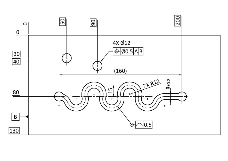
meandering_line_tolerance_example_Drawing_v1-page-001_1_y9ivfh.jpg
 
Replies continue below

Recommended for you

Peter Sommer,

You did not state which standard you are going by. If ASME, the latest version ASME Y14.5-2018 includes a provision for a dynamic profile tolerance modifier. If it is ISO, I believe there is a similar modifier/control.

First off, the profile tolerance should be applied to the surface of the slot, not the center line. Profile tolerances control surface variation not derived theoretical geometry like center lines (glossing over the fact that actually this is not really a center line as that would be a theoretically perfect line, deriving the shown center geometry for an actual as-produced slotted feature shown I think would be a non-trivial process).

how do I indicate a tolerance for a constant width (within 0.1mm) of the slot?
I think dynamic profile, combined with basic dimensions (remove the 8+/-0.2 directly toleranced width) would meet most of your requirements. It would provide a more strict control of the exact path of the slot, however it unambiguously provides "constant width". If this is not an option then I think unfortunately holding the entire slot to a standard fixed profile tolerance is most clear cut method. A +/- directly toleranced width combined with a profile tolerance to control the path of the slot would get you well into the weeds of what it means to combine profile and directly toleranced dimensions.

how do I indicate the the slots centerline ending at center of the holes?
There is no built in geometric tolerance that directly communicates this. This would be accomplished through proper tolerancing of the slot and its ends. My opinion would be that the ends should be included in an all-around profile tolerance of the slot unless you have a compelling reason otherwise.

Peter Sommer said:
Is it wrong to make the "4X Ø12" when two of the holes are connected with the slot?
Theres nothing inherently wrong with it no especially since when considered alone these holes/end-points are FOS, but again my opinion would be that the ends should be included in an all-around profile tolerance of the slot unless you have a compelling reason otherwise.

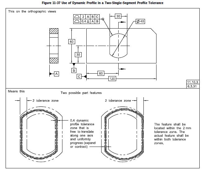
Below is an example of dynamic profile from Y14.5-2018:

dynamic_profile_xvn5ym.jpg
 
chez311,

chez311 said:
If ASME, the latest version ASME Y14.5-2018 includes a provision for a dynamic profile tolerance modifier. If it is ISO, I believe there is a similar modifier/control.

Do you know which is the equivalent modifier in ISO? I am using ISO for my gauge design work, but I am not saying I am particulary familiar with that system. Thanks
 
Andera,

I believe it is 'OZ' or Offset Zone (or more accurately the "unspecified linear tolerance zone offset").
 
Peter Sommer said:
my questions are as follows;

1. how do I indicate a tolerance for a constant width (within 0.1mm) of the slot?

I am assuming ASME Y14.5. If your intent is to have an accurate slot width, then it is a feature of size. Your specification of 8[±]0.1mm is completely inspectable. Your profile tolerance should be applied to one side of the slot, not the centreline. 2[×][ ][box][⌓][/box][box]0.5[/box][box]A[/box]. The centreline is imaginary. The 2[×] controls the opposite side. I think you need at least one datum feature.

Peter Sommer said:
2. how do I indicate the the slots centerline ending at center of the holes?

Your profile tolerance controls the centre of the slot to within 0.5mm. If this is not accurate enough at your holes, read up on non[‑]uniform profile tolerance zones. I see this terminology in ASME Y14.5[‑]009 attached to Fig[ ]8[‑]11. In ASME Y14.5[‑]2018, it is Fig[ ]11[‑]8, and the caption says "Specifying Different Profile Tolerances on Segments of a Profile".

Peter Sommer said:
3. Is it wrong to make the "4X Ø12" when two of the holes are connected with the slot?

Technically, it is not wrong, and I cannot see an alternate, incorrect way to interpret your drawing. The holes may well be drilled with the same tool on the same setup. Two separate "2[×][ ][⌀]12" are clearer, and less likely to result in time wasted in phone calls with your fabricator.

--
JHG
 
As chez311 noted, the profile of a line tolerance cannot be applied to the center of the meandering slot. Profile of a line controls line elements of surfaces (of any shape).

There is an All-Around symbol at the leader. Perhaps the profile tolerance was intended to apply on the (line elements of the) surfaces anyway, otherwise, it makes no sense (the centerline doesn't make an "around" contour). In the case that it's All-Around it will control both the width of the slot AND it will include the two holes at which the slot starts and ends.
The profile tolerance cannot be used in conjunction with the toleranced dimension of the width of the slot (which should not necessarily be interpreted to apply along the entire slot anyway, I would be more inclined to interpret it to apply on that straight-parallel segment of the slot).

Note that without datum references, the profile tolerance does not locate or orient the slot.

The drawing doesn't show what feature is datum feature A.
 
Thank you all for your input.

To clarify some missed info in my first post

- I am working according to ISO standards
- The A datum was lost in translation and should be placed on the top line

I have not really solved the problem yet - although there was many good input. I will post an update when I make a little more progress.

 
Status
Not open for further replies.

Part and Inventory Search

Sponsor