Continue to Site

Eng-Tips is the largest engineering community on the Internet

Intelligent Work Forums for Engineering Professionals

  • Congratulations KootK on being selected by the Eng-Tips community for having the most helpful posts in the forums last week. Way to Go!

Measuring flatness of primary datum in constrained condition? 1

Status
Not open for further replies.

ryanwolff90

Mechanical
Apr 30, 2013
5
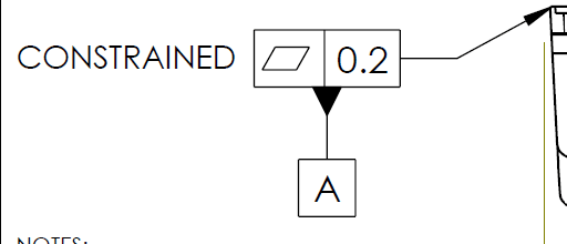
A principal engineer at my company always adds the word 'CONSTRAINED' next to a flatness callout on plastic parts for the Datum A feature, as shown in the picture attached. When I asked him about it, he explained that this allows the vendor to apply some pressure to the part when measuring flatness. I keep insisting that this approach isn’t valid and we need to clearly specify how the part should be constrained, rather than leaving it up to the vendor. For example, we could state something like, 'Permissible to measure part while constrained to a flat surface plate on Datum A using screws through Datum B holes torqued to X in-lbs.'

One question I have, though, is: how do you actually measure the flatness of a feature if it’s constrained to a flat surface on that same feature? I found a post from 2020 discussing measuring flatness in both the free state and constrained state, but it didn’t address the method of measuring the part while it’s constrained.
Thank you!
 
Replies continue below

Recommended for you

Screenshot_2024-08-21_150528_unf91u.png


My favorite was an optical method where the part is held against a piece of glass that is the bottom of a shallow bucket also containing a translucent liquid. A camera records the amount of occlusion by the liquid as a measure of depth. It's very fast, but requires some setup and calibration.

Anything can be perfectly flat if pushed hard enough. There should be a specification of how hard and where the supplier is allowed to push.
 
Hi, ryanwolff90:

What is datum feature A? I don't see a flat surface where your arrow points to.

Best regards,

Alex
 
ryanwolff90,

Look up flexible features in the standard. When I prepare drawings for flat plates or sheet metal, more often than not, I specify that the primary datum applies when the face is clamped to a flat reference surface. I would also think that restraint either is required, or not permitted.

The word "RESTRAINTED" is not an adequate description of how the piece is to be fixtured.

--
JHG
 
The method you suggest over the principle engineer's simple 'Constrained' is more accurate and true to the design intent. It might require more time to validate and may require an inspection fixture vs someone just pushing down on the part to make sure the surface sits flush on the flat surface. I guess it depends on how critical that requirement is. If it's a gasket or sealing surface that seals in liquids or pressure it might require more definition.
 
These should reflect the as-installed condition.
 
The term is "restrained" and not "constrained" - which relates to something different in tolerancing. And you are correct that there must be a detailed restraint requirememt if a restrained condition is specified.

Usually with restrained condition, all requirements apply in that condition except those modified at the free state by the free state modifier.

A wire gage, if practical, could be used to inspect the flatness of a datum feature surface when it is restrained against a datum feature simulator.
 
Burunduk - Just curious, how would you use a wire gauge to inspect the surface flatness? I'm guessing I'm thinking of the wrong type of "wire gauge".
 
Ryan,

I have faced the same problem with oil pump cover plates. You are correct that simply stating "constrained" is not good enough, and the constraining method should be clearly agreed and specified. You can work out a method with a trusted supplier. It should respect the function of the part, the manufacturing process, and the inspection method. The way I've done it in the past is to establish a number of datum targets on the datum surface for inspection fixturing (it can be more than 3, but they need to be chosen carefully considering the part flexibility and the fixture clamping force), and then establish flatness measurement zones in between them. I hope this helps.
 
Mech1595,
Suppose that flatness within 0.2 mm is specified (as in OP's image).
You can use a 0.2 diameter gage wire and try to insert it between the examined surface and the planar fixture base to which it is restrained. If you can, the part fails inspection. If you can't, it passes. The downside is that you'll only detect the deviations accessible from the periphery, so if the surface is concave enough you may pass a bad part. On the other hand, a flatness concern is often about convexity (for ensuring stability and/or sealing), so it might be OK.
 
If sealing only at the extreme periphery is required then the flatness is not needed for the entire surface and should not be called out for the entire surface. Using a gauge wire or feeler gauge is not going to be reliable for a restrained part when the restraint is not specified. At least with liquid tank all parts of the surface are observable.
 
3D said:
Using a gauge wire or feeler gauge is not going to be reliable for a restrained part when the restraint is not specified.

If the restraint is not specified, the part must not be restrained, period. Regardless of a feeler gage or some other method.
 
"If the restraint is not specified, the part must not be restrained, period."

Which is why I said that it should be specified. Otherwise it is up to the supplier to decide based on the stated vague requirement. There is nothing in the standard that says "must not"

"There should be a specification of how hard and where the supplier is allowed to push."


For the datum features to comply with the physical datum feature simulators, forces may be applied in accordance with the specified restraint requirement to flex or deform the part

In this case no forces are specified. As a practical matter, they should be. As a standard manner they don't need to be.

7.20.1 Specification of Restraint Magnitude
The allowed or required magnitude of force (clamp load, torque, etc.) or condition used to restrain a part may be one of the following:
(a) the magnitude necessary to restrain the part on the physical datum feature simulators. See Figure 7-49.
(b) the magnitude of the load that the part is subjected to in its installed condition.

I am missing the word "shall" in that. Do you see it?
 
A Fundamental Rule in ASME Y14.5-2018:

"(n) UOS, all dimensions and tolerances apply in a free state condition. For exceptions to this rule, see subsection
7.20."
 
3DDave, let me help you with that:

"(n) UOS, all dimensions and tolerances apply in a free state condition. For exceptions to this rule, see subsection
7.20."

Therefore - "If the restraint is not specified, the part must not be restrained, period. Regardless of a feeler gage or some other method."

I hope that this clarifies that your questions and questioning are out of place.
 
That isn't a correct response to the OP. There is a badly stated requirement for restraining the part. That is the problem to solve.

The only footing you have is to reject the entire drawing. That's it. Because it uses a word you dislike and one that does not appear in the standard the drawing, for you, is therefore entirely uninterpretable. But that's not the direction you have taken and it looks like you are just picking another fight.

No one asked for that answer because the clear intention of the drawing creator was the part shall be constrained when validating that feature. The drawing creator did a poor job of it, but it would be unprofessional to turn the part back and say, we inspected in the free state and it failed inspection. The professional act is to get clarification as to how the part is to be constrained or restrained and have the drawing modified accordingly. This was my suggestion before you chimed in.

A reader has written "I've read the definitions for constrain and restrain but am still having difficulty knowing when to use which word. Can you help?"

Editor Paul Wood responds:

There is some overlap in the meaning of the two words.

Both can be used in the senses of holding something back by force or of limiting or restricting one's actions.

The standard chose one of the two; it doesn't exclude the other any more than the fact the standard uses "free" and "unrestrained" to mean the same thing isn't clearly contradictory.
 
3D,
I gave a detailed and reasoned response to the OP at 23 Aug 24 08:08, addressing everything he asked about.
 
3D said:
If sealing only at the extreme periphery is required then the flatness is not needed for the entire surface and should not be called out for the entire surface

I would have to kindly disagree with that. The surface could be near-perfectly planar near the edges but with a convex deformation in the middle, therefore performing poorly at providing orientation to the part as a main functional interface (and a primary datum feature), and at sealing if relevant.
 
Status
Not open for further replies.

Part and Inventory Search

Sponsor