Eng-Tips is the largest engineering community on the Internet

Intelligent Work Forums for Engineering Professionals

Measuring V Grove length ACCUARATELY 4

Status
Not open for further replies.

Vikram 1971

Industrial
Sep 24, 2020
12
0
0
IN
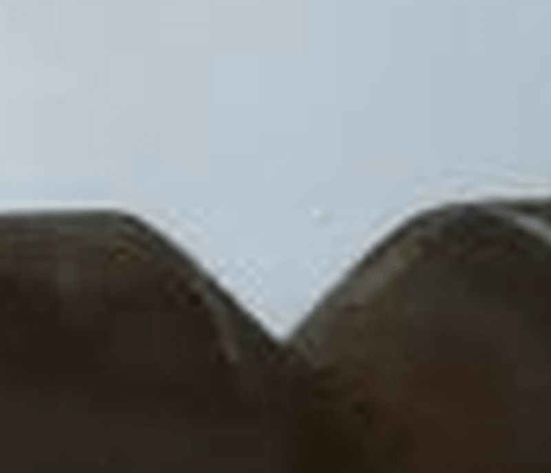
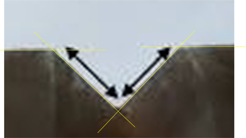
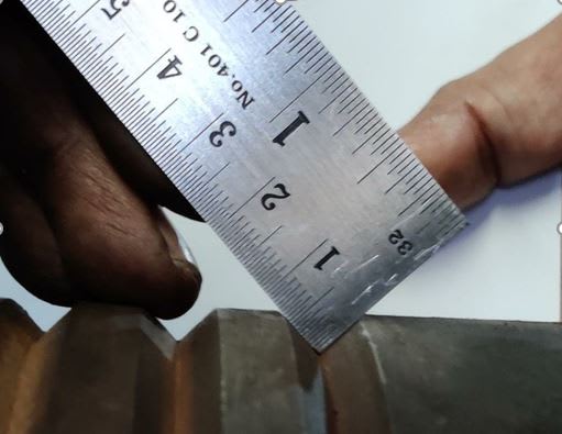
Below is the image of a hot steel rolling mill roll having V Groves.

Capture_fe9gxh.jpg


I am trying to measure the length of each side of the grove as shown in the figure accurately.

Capture2_sdwdvt.jpg


Currently I am using a normal ruler but as you can see it not accurate.

Any other proper way of measure the grove length accurately, hence checking the symmetry of the groves????
(Any different tool or caliper? ?)
 
Replies continue below

Recommended for you

Vikram 1971:
Take a sharp pointed dividers from your drafting tools kit, and put one tip in the bot. of the groove. Open the dividers to match one of the slope lengths, swing the dividers to check the other slope at that point. Measure the dividers tips with your ruler or a caliper, or some such, and average the two readings at that point. Do this at a number of different points on the roller and average those. You should be able to get a pretty good measurement reading on a ruler to +/-.01” or .02” by eye. The measurement on the two mating rollers won’t be the same, as a function of the material thickness you are rolling and the wear on the two rollers. Have a good friendly, local, machinist do it. They’ll know how.
 
It almost seems to me that measuring directly on the posted photograph might make more sense. Most of the "tools" are rather coarse, but you could hypothetically image the groove with nearly 0.2 inch resolution, assuming 1920 pixels across the top of the groove.

TTFN (ta ta for now)
I can do absolutely anything. I'm an expert! faq731-376 forum1529 Entire Forum list
 
Many options for this measurement. depends upon how often you will check and the accuracy needed. Optical comparator, self-made go / no-go gage. Place a known sphere diameter in the groove and measure its height from the surface. Then with some math, some of the geometry of the groove can be determined. A coordinate measuring machine can do a little better than the ruler. A depth mic with an angled tip to get to the bottom of the groove to measure the depth. I'm sure there are many other methods that can be used.
 
How accurate do you want to be, aka how much do you want to spend? You can use a groove micrometer or groove caliper, optical comparator, or even laser scanner if you want to be really accurate.
 
It seems to me that your primary issue is not the measurement, per se, it's the measurand, i.e., the reason you are having measure the groove dimensions is because the grooves you took a picture of are horribly machined. By any measure, the groove on the right in the first image is very ill-formed

groove_fgj5ht.png


TTFN (ta ta for now)
I can do absolutely anything. I'm an expert! faq731-376 forum1529 Entire Forum list
 
This advice may not be valid depending on the accuracy you need to achieve but you might find point vernier calipers do the trick. Alternatively, spring calipers (probably straight legs) might be used in correlations with an inside micrometer to transfer and then measure the distance. The final option I can think of easily would be to use a coordinate measuring system (also known as a multiaxis measuring system) probably coupled with a rather fine point again. Many tooling companies will have one of these in the metrology lab as they're quite versatile for more difficult measurements.
 
I'll agree with bcd on this and suggest the best option as an optical comparator.

You will also be able to see the defects- as your second groove in that picture is not conforming.
 
@IRStuff, the part seems to be cylindrical. The "ill-formed" edge of the groove is actually of a circle curving away from you as far as I can tell.
 
Are they threads or straight grooves? Either way, as someone above mentioned "measurement over pins" is commonly used with gear teeth.
 
the part seems to be cylindrical.

Yes, pretty obvious, now that you point that out. So, imaging would still be the most accurate, although getting the angle and orientation correct would be the biggest challenge. The other groove in the same image is almost straight-on. There are dimensional measurement imaging systems that have software to do the calculations for finding edges, etc. I used ImageJ's Canny edge detector on a zoomed in version of the OP image for the second image below.

groove2_c4glgy.jpg

groove3_g4igoi.jpg


TTFN (ta ta for now)
I can do absolutely anything. I'm an expert! faq731-376 forum1529 Entire Forum list
 
depending on what equipment and tools and how accurate the measurement required.
most simplest is to measure the correct angle, if it is correct measure the width of the groove. more accurate is optical comparator with certified screen Mylar with grid measurements, also you can draw it in cad, print it out on a mylar and place it on a optical comparator. most comparator have different sizes, eg 10 X 20 X ect.
 
Thanks everyone for such an overwhelming response. Never imagined that there are so many ways to measure it.
Sorry that I cannot thank you guys much sooner.

dhengr said:
Take a sharp pointed dividers from your drafting tools kit, and put one tip in the bot. of the groove. Open the dividers to match one of the slope lengths, swing the dividers to check the other slope at that point. Measure the dividers tips with your ruler or a caliper
I tried doing this and I was able to get some measurement. Easiest Method​


IRstuff said:
So, imaging would still be the most accurate, although getting the angle and orientation correct would be the biggest challenge.
Thanks IRstuff for the method and I tried it. Clicked some pictures and yes, angle and orientation problem is there. It take some amount of time to align the camera. But this method is pretty accurate​

mfgenggear ,FACS suggest to use optical Comparator. But sadly, I got no optical comparator.

Thanks dhengr, IRstuff , Scuka, rather_be_riding and others. Everyone was so helpful,
Thanks everyone!!!!!


Status
Not open for further replies.
Back
Top