Hi All, I am learning about gears and I was hoping that you could help me with a question regarding mechanical advantage. I'm confused on 1 issue with 2 different examples -

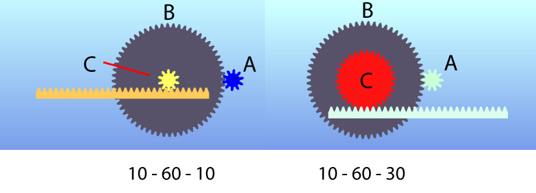
The "A" spur is the input gear, I'm trying to work out the torque that the "C" spur gear will have onto the rack. I understand that the bigger the PCD of the "C" spur, the faster the rack will move, but the relationship of "B" and "C" seems to be that of a class 2 lever where they are attached and share the same fulcrum, the load is in the middle "c" and the effort on the outside "b". So in the right version (10-60-30) would the mechanical advantage be 6:1 for the A-B gear X 2:1 for the B-C lever? 12?

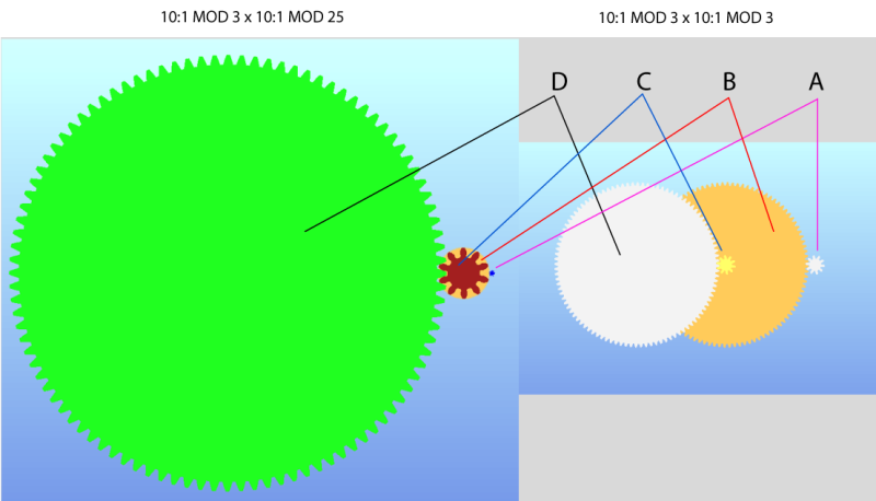
This image has the same 10:1x10:1 reduction in both versions, but on the left version the mod was changed. "A" is the input gear. I understand that both of these setups will have the same reduction in rpm. But the relationship between B and C looks like a class 2 lever.
My confusion started after reading this
which says that torque ratio = gear ratio = mechanical advantage.
So if both these setups have the same gear ratio and the relationship between B and C in each setup is vastly different, how can they have the same torque ratio?
So my question is - Can gears that are fixed to each other, on the same axis, be classified as a class 2 lever based on PCD and is that taken into consideration when calculating the mechanical advantage of a gear assembly? and if not taken into consideration, why not?
I appreciate your help, I want to understand the rules before I do the maths.
Thanks

The "A" spur is the input gear, I'm trying to work out the torque that the "C" spur gear will have onto the rack. I understand that the bigger the PCD of the "C" spur, the faster the rack will move, but the relationship of "B" and "C" seems to be that of a class 2 lever where they are attached and share the same fulcrum, the load is in the middle "c" and the effort on the outside "b". So in the right version (10-60-30) would the mechanical advantage be 6:1 for the A-B gear X 2:1 for the B-C lever? 12?

This image has the same 10:1x10:1 reduction in both versions, but on the left version the mod was changed. "A" is the input gear. I understand that both of these setups will have the same reduction in rpm. But the relationship between B and C looks like a class 2 lever.
My confusion started after reading this
which says that torque ratio = gear ratio = mechanical advantage.
So if both these setups have the same gear ratio and the relationship between B and C in each setup is vastly different, how can they have the same torque ratio?
So my question is - Can gears that are fixed to each other, on the same axis, be classified as a class 2 lever based on PCD and is that taken into consideration when calculating the mechanical advantage of a gear assembly? and if not taken into consideration, why not?
I appreciate your help, I want to understand the rules before I do the maths.
Thanks
