Rodrigo Benitez
Civil/Environmental
Hi engineers, I don't know if this is the best forum to post this question, but here it goes.
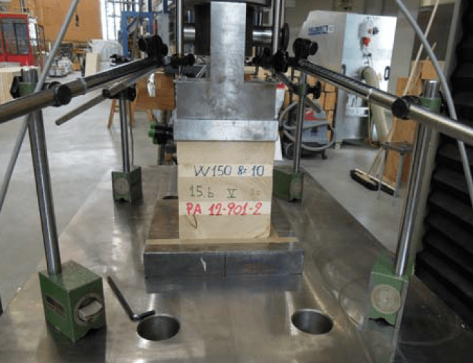
Regarding about a compression test on a sample with an hydraulic press: what's the real difference between using 4 LVDTs to measure displacement (like the one of the photo below) compared to using only the actuator's internal displacement transducer? Would it cause a higher displacement measure to use the second method, and hence, a loss in stiffness? This photo is from another author:

I'm wondering about this because I carried out this same compression test of the photo, but measuring the displacement by the second method, and I'm thinking it might be the cause of the big nonlinear-elastic part of my experimental curves:

The black lines are FEM modelling. As you can see, they are much stiffer then the experimental curves. I would really appreciate if you could share any knowledge/literature/article discussion this.
Thanks in advance
Regarding about a compression test on a sample with an hydraulic press: what's the real difference between using 4 LVDTs to measure displacement (like the one of the photo below) compared to using only the actuator's internal displacement transducer? Would it cause a higher displacement measure to use the second method, and hence, a loss in stiffness? This photo is from another author:

I'm wondering about this because I carried out this same compression test of the photo, but measuring the displacement by the second method, and I'm thinking it might be the cause of the big nonlinear-elastic part of my experimental curves:

The black lines are FEM modelling. As you can see, they are much stiffer then the experimental curves. I would really appreciate if you could share any knowledge/literature/article discussion this.
Thanks in advance
