Eng-Tips is the largest engineering community on the Internet

Intelligent Work Forums for Engineering Professionals

Mechanical Vibration on API Pump VS4

Status
Not open for further replies.

Mike9208

Mechanical
Feb 23, 2023
12
0
0
HK
Dear Colleagues,

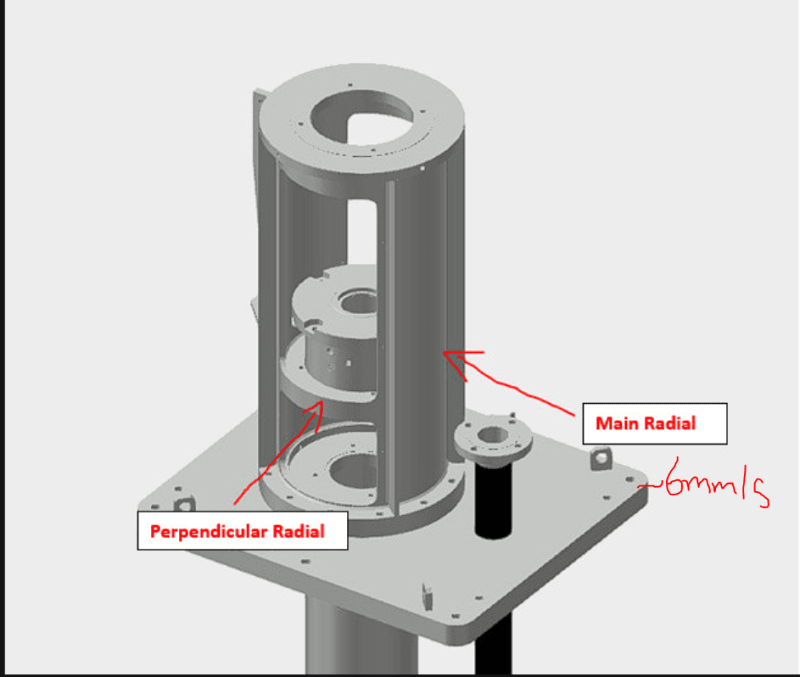
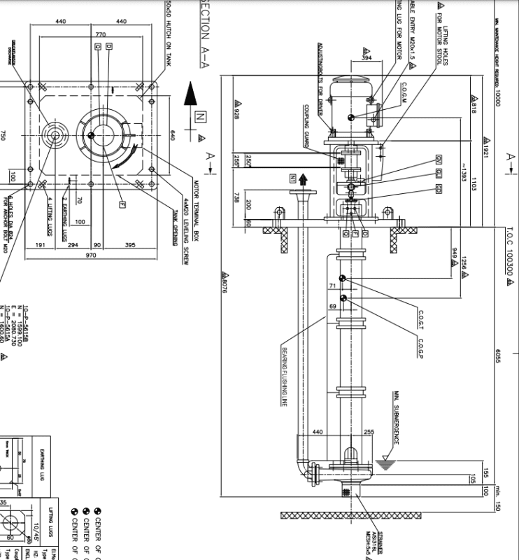
Looking for some advice. On the plant where I work, we have an API 610 VS4 pump. The pump is having high vibration only in one radial direction (almost 6mm/s - too high for a newly commissionned mechine), while axial and other radial vibration are within ISO limits.

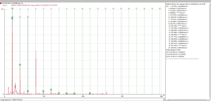
This pump was originally supplied with lubrication to the bushings from the same discharge of the pump. Our first thought was that during commissioning stage the process fluid was not clean enough and could bring some particles to the carbon bushings. so we dissasembled the pump, we found some corrosion and therefore we fabricated new bushings. Also we changed the lubrication method to have external treated water line. Despite these efforts, the pump is still having high vibration as shown in the attached spectra.

I would like to ask your advice and recommendations on:

1. If with available vibration measurement is possible to have any conclusion on the possible causes.
2. What additional vibration measurement (phase, nyquist, etc) could give more light on the root cause.

VS4_Pump_GAD_agjrfz.png
Radial_other_direction_pump_xgk0ty.jpg


Appreciate any help
 
Replies continue below

Recommended for you

There are 2 plots. An attachment plot and an embedded plot within the post.

The attachment plot shows high 1X up to 6mm/sec and all other peaks much much lower.

The embedded I can't really see as well but it looks like 0.7 mm/sec at 1x. The remaining peaks are higher relative to this 1x, but still tiny relative to the 6mm/sec on the first plot (the attachment plot).

What is the relationship between these two spectra? The same location at two different times, or two orthagonal directions taken at the same time?

If it is the latter (two spectrum taken at the same time in orthagonal directions), then the high directionality of the 1x component would lead me to suspect structural resonance.
 
hi electricpete,

Thanks for your valuable comments.

The two spectra are as you indicated in last sentence, same time in orthogonal directions:

two_directions_hps1ek.png


Tthe 1x high peak and directionality also leads us to suspect resonance. Is there any additional vibration measurement in your opinion that could confirm or discard this hypothesis?
 
How does this vibration compare to speed then? If it's on a VFD, going slightly slower or faster tends to have drastic effect on resonant vibration. Because this is a long overhung rotating machine, the machine builder owes you some criteria for the stiffness of them mounting surface - has this been met? Is the mounting surface sufficiently flat and free of prestress? The first resonance mode would be easily determined by comparing vibration amplitude moving up and down from the mounting surface.

Motion amplification may be useful here too. It's the hurried/poor man's ODS analysis.
 
Hi Geesaman.d

This pump runs without VFD.

if we took measurements moving up from mounting surface to compare amplitude, and supposing it was a resonance issue, what would I expect to see in the amplitude? around zero at bottom and max amplitude in the top of the motor?
 
The amount of vibration will increase as you move away from the flexible region (my first suspect is the mounting surface). On a machine like this, it would have the most movement radially down at the suction housing and at the top of the motor. If the machine itself is plenty stiff, the vibration amplitude will be proportional to the distance from the mounting surface.

By no means are most resonances this easy to diagnose, but for overhung rotating machines I always start there.
 
I'd make some vertical measurements all over the base plate.
If the design and installation is correct in my opinion the vibration should be very low. Like <.5 mm/sec rms.

The callout for M20 "leveling screws" in the drawing suggests to me the base plate may be "supported" at just a few points, even if after leveling it was grouted with good workmanship.
Sometimes millwrights install "leveling nuts" on the anchor bolts under the base plate. That technique is good for leveling signs and light posts in a parking lot, but will leave a rotating machinery base free to shimmy no matter how hard the anchors are tightened.

Then the there are the angle support beams/joists shown in the drawing.
That support structure is guilty until PROVEN innocent.
A simple " bump test" can reveal "reed" resonant frequencies.
Some analyzer even allow testing with the machine running.

Rigid couplings with dirty faces can become a "bent shaft" that mechanically cranks the pump/motor.

Sometimes trim balancing weights at the top of the motor ( fan or clutch) can reduce the 1X vibration even with a poor design or installation.
 
Hi Mike,

1. If with available vibration measurement is possible to have any conclusion on the possible causes.
- Can't rule everything out, it does narrow it down
- I'd sgguest that "whats left" list is
* Imbalance
* Mis-alignment
* Looseness (could be soft foot, resonance, loose bearing block etc)

2. What additional vibration measurement (phase, nyquist, etc) could give more light on the root cause
I'm not sure your background in V.A. but just google the above and you'll find various guides on how to measure for those things.

I'd suggest chase down the above 1 at a time starting from easiest to hardest
easiest is to tight all the hold down bolts etc and see if it has an effect.


Andrew O'Neill
Specialist Mechanical Engineer
Australia
 
The 1x high peak and directionality also leads us to suspect resonance. Is there any additional vibration measurement in your opinion that could confirm or discard this hypothesis?
Factor of 8.5 difference in 1x component (6mm/sec and 0.7mm/sec) in the 2 radial directions on a vertical machine, it's a slam dunk resonance imo.

We can also see that the tall cutouts in the stool supporting the motor would create an enormous difference in stiffness in the 2 radial directions.

As Tmoose suggested, bump test is a typical step for checking resonance. Bump in both directions for comparison and I'm sure you'll see a big difference in natural frequencies. Bump test while secured on a vertical machine might be a little off due to mass of the fluid but should be close to accurate.

I have to pause for a moment to think about which direction is stiffer and accordingly which direction we expect to be higher in frequency.
[ul]
[li]First gut reaction is the 6 mm/sec direction is stiffer since that's where all the metal is. [/li]
[li]But second thought is that it resembles 2 plates, and those plates are stiffer when bending in the 0.7mm/sec direction than when bending in the 6 mm/sec direction.[/li]
[/ul]
I lean towards the second-thought conclusion (stiffer in the 0.7 mm/sec direction based on the way the two plates bend), but either way if you see a big difference in resonant frequencies and natural frequency near running speed in the 6mm/s direction then that's your confirmation.

Another option for checking resonance is coastdown test to see the pattern of magnitude and phase changes to see if that matches resonance.

Another option I like is trying to apply temporary stiffening in the high-vibration direction and see how the 1x changes (maybe wedge a board in somewhere to try to stiffen it). If vibration magnitude changes significantly from stiffening, that's somewhat of a confirmation that you have resonance. If it changes monotonically in the decreasing-magnitude direction as you stiffen, that tells you that stiffening will be a good permanent solution. Alternatively dynamic absorber.

It wouldn't hurt to map the base vibration as Tmoose suggests and he also mentioned angle supports/joists... I don't see them but if you've got any existing supports I'd check to see if they are tight.


Thank you all for the valuable comments. A lot of information to process, I dont have background as VA but this problem now is under my plate so I appreaciate all the feedback and recommendations... I will start by checking the installation (alignment, TIR, leveling) and then I will see the best way to do the bump test. I will inform here as I have more relevant data/conclusion
 
Attached is an image based on the OP's pump "drawing" .

4 leveling bolts in the corners, but no indication of grout etc to create full support for the base plate. If so, and there are gaps between the base plate and the tank top, and the six anchor bolts will try to close gap at least locally around each anchor.
So the pump assembly resembles a hair brush sitting bristles down on a table.


It appears the 60 mm thick base plate is mounted directly to a tank opening.
The tank opening may be stiffened by 200 X 200 x 50 mm angle ? 8" X 8" X 2" ?
May be a frame around the opening. Maybe some of the angles extend (TBD) to decent vertical supports.
Or not.
 
Status
Not open for further replies.
Back
Top