Continue to Site

Eng-Tips is the largest engineering community on the Internet

Intelligent Work Forums for Engineering Professionals

  • Congratulations cowski on being selected by the Eng-Tips community for having the most helpful posts in the forums last week. Way to Go!

Melt Thru Weld Symbol 1

Status
Not open for further replies.

memoi567

Mechanical
Jan 23, 2020
7
Hi,

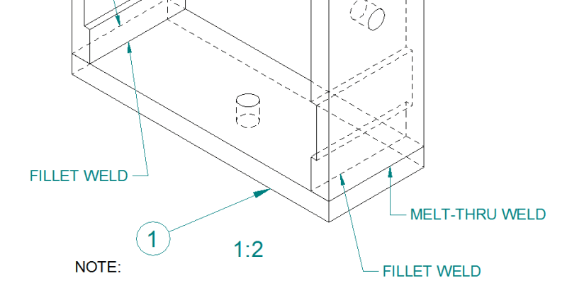
I came across the following in one of our drawings. This is very different to how I would normally callout a weld on my drawings. I've never heard the term Melt-Thru Weld before. I know what symbol to use for the fillet weld, but I don't know how to callout a "Melt-Thru Weld". If you had to correct this drawing how would you do it?

Capture_vnsphg.png


Regards,
 
Replies continue below

Recommended for you

I am not a welder by any means, but I've been designing weldments for 40 years. Never heard the term "melt-thru weld".
 
The drawing is simply wrong.

If you are using American Welding Society (AWS) requirements the correct term is "complete joint penetration" (CJP).

However that is not a drawing weld callout.

Google will find for you many pages showing weld callouts. However welding joint design is not a topic that should be done by the combination of inexperienced designer + Google.

From the drawing provided I could only guess at the correct callout because there is too much undefined about what is needed. So I will not offer a suggested callout.
 
@IRstuff thanks for your help, but those two websites didn't really help me. In case anyone is curious as to the solution I came up with I just put a Bevel weld symbol in place of the melt thru. I called up our fab shop and this is what they have been doing when they see this drawing. It's absolutely mind boggling to me that this drawing has been in circulation for the past 7 years without anyone mentioning the unorthodox weld call-outs.
 
Also not good practice to indicate weld to hidden line. Weld symbol above and below the leader line typically refers to near side and far side of arrow indicated joint.

Ted
 
@hydtools agreed

@MintJulep You have no idea the amount of incorrect drawings I find on a daily basis.
 
The melt through symbol is used in conjunction with a groove weld symbol. The groove weld symbol is placed on the side of the reference from which the weld will be deposited. The melt through symbol, a hemisphere that is shaded in, is placed on the side of the reference line opposite the groove weld symbol. The intent of the melt through symbol is to indicate the weld is complete joint penetration. There is an option to indicate the amount of melt through, i.e., root face reinforcement, by placing a "size" to the left of the symbol. If the base metal is thin, the groove could be simply a square groove. Thicker material would required a bevel, V-, J-, etc. preparation,

Maybe the attached file illustrates the melt through symbol better than my verbal description.


Best regards - Al
 
 https://files.engineering.com/getfile.aspx?folder=703463ba-45b3-4dbe-90a0-c39d5c1130a6&file=V-Grv_w_Melt-thru__1-June-2020_Model_(1).jpg
Status
Not open for further replies.

Part and Inventory Search

Sponsor