Continue to Site

Eng-Tips is the largest engineering community on the Internet

Intelligent Work Forums for Engineering Professionals

  • Congratulations KootK on being selected by the Eng-Tips community for having the most helpful posts in the forums last week. Way to Go!

Merging pipelines from different operating pressure vessels 3

Status
Not open for further replies.

aegis4048

Petroleum
Apr 23, 2024
35
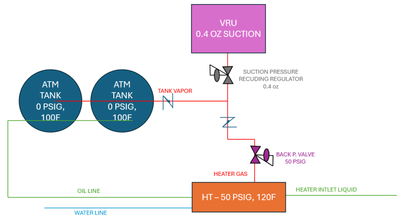
Hi, I have a simple upstream wellsite facility design, shown in the below image.

Liquid comes from an HP separator (not shown) into the heater operating at 50 psig, 120F. The pressure on the heater is maintained by the back pressure valve set at 50 psig. The separated oil from the heater goes to the atmospheric oil tank. The water line is irrelevant here.

There are two gas lines: one from the atmospheric oil tanks (0 psig) and other from the heater (50 psig). My colleague came up with a design of merging these two lines into one, therefore capturing flash vapors from tanks and the heater through a single VRU (oil flooded screw compressor). The suction control valve will maintain the inlet pressure to the VRU in the range of 0.4~0.8 oz. I'm curious how the two gases from different pressure vessels will merge together. There will be check valves from both sides to prevent back-surge.

Q1) Will the vapors from tank be able to smoothly merge with 50 psig heater gas, and flow into the VRU suction together?
Q2) Will the 50 psig pressure from the heater exert back pressure on the tanks, causing it to vent to air instead of flowing into the VRU suction?
Q3) If this is not gonna work well, what can be down to remedy this?
Q4) bonus question, but if anyone has an example vapor recovery P&ID and can share with me, that would be great (aegis4048@gmail.com)

I'm asking this because usually there's a separate booster compressor for heaters (30~50 psig) and another VRU for tank & VRT vapors (0~3 psig).

diagram_g2zzvz.png
 
Replies continue below

Recommended for you

"I'm asking this because usually there's a separate booster compressor for heaters (30~50 psig) and another VRU for tank & VRT vapors (0~3 psig)."
That is the better way of recovering these LP vapor streams - saves on overall compression power.

 
@georgeverghese
Can you explain more? By compression power you mean fuel gas or electricity consumption to run engine & motors?

The problem with having multiple compressors is the additional rental cost for operators that don't own compressors.
 
Atm tank vapors will not enter the VRU when its inlet pressure is > 0 psig.
When heater pressure is <50, your BPvalve is closed. VRU takes from tanks. Tanks at vacuum?
When heater pressure is >50, your BPvalve is some % open and, if tank outlet check valve fails, tanks are overpressured.

Apparently your atm tanks experience whatever heater pressure is at all times through oil line and become Overpressured. How do you keep heater pressure off your atm tanks? Missing a downstream pressure control valve in the oil line.

When VRU pressure is >4oz, VRU Inlet Pressure valve is closed. Tanks receive full heater pressure through oil line, or broken check valve. You should never assume check valves always maintain seal against reverse flow.

Tank relief valves are not to be used to as process valves.

--Einstein gave the same test to students every year. When asked why he would do something like that, "Because the answers had changed."
 
By compressing the additional volume of HT offgas at stage 1, this LP VRU compressor will have a larger duty.
If you are renting these compressors, then agreed, you may need to do some economics calcs to see which option is cheaper, with the cost of power to run compressors included in the calcs.
 
Whilst you show your tanks as 0psig, what actually are they designed to?

If it is "atmospheric" then you will not get any flow until the inlet pressure of the VRU falls below 0psig, I.e. negative pressure. The issue then is that you could easily implode the tanks. Or drag air into the tanks.

Your 50 psig is inside the heater. The pressure downstream the valve will be whatever the inlet to the VRU is plus frictional losses. This could be enough to prevent gas from the tanks flowing towards the VRU.

Q3, many options, but separate entries into the VRU are needed. Without knowing what your max tank pressure is, you can't really move forward.

Remember - More details = better answers
Also: If you get a response it's polite to respond to it.
 
Think API 650 tank design pressure is not suitable at all for VRU application. Go for API620 instead - much more operating room. You will be struggling to find operating pressure headroom with API 650 tanks.
 
Some 650 tanks are designed for a bit more than 1kPa. But you need to know what it is. But it won't be high and you need very large ducting usually.

Remember - More details = better answers
Also: If you get a response it's polite to respond to it.
 
@all
The tanks are probably API650 tanks rated at 2.5 psig. The upstream operators usually try to maintain 16oz or below pressure on atm tanks. Thief hatches are usually set at 10~14 oz, and PRVs slightly lower than thief hatch. I understand that there isn't much operating margin to ensure substantial pressure differential among vent, flare or VRU suction, but this is usually what we get (for this reason I've heard that some big operators are trying to use 3 psig, instead of 16 oz, tanks to completely remove venting events).

Blanketing gas or vacuum safety valves usually trigger 0.4~4oz to prevent implosion.

@1503-44

"Apparently your atm tanks experience whatever heater pressure is at all times through oil line and become Overpressured. How do you keep heater pressure off your atm tanks? Missing a downstream pressure control valve in the oil line."
-> By control valve, are you suggesting installing a pressure reducing regulator in the oil line to the tank? There's usually no pressure regulator on the liquid line, the only control valve on the liquid line dumping to the tanks are usually liquid dump valves. It's usually connected to some float operated switch that fully open valves to "dump" (or it can be more fine-controlled with advanced control device, such as % open). Neither I and my colleague (he has much more experience than me) have seen pressure regulators on the liquid side.

@LittleInch
"separate entries into the VRU are needed"
-> I think you are approaching this in the right direction. I called my colleague again and he said that it's possible to install a 3-way control valve connected to a PLC system. The gas from HT and tanks will merge into the 3 way valve, and to the inlet of the VRU. But that valve will have a control logic that temporarily shuts off inlet stream from one side, and open the other inlet stream. For example, initially in the 3-way valve, the valve connected to the tank side is open, while the HT side is closed. When the pressure in the HT is built above set point, the valve for the tank side closes and the valve for the HT side opens. This achieves three things:
1) prevent over-pressurization in both tanks and HT
2) maintain independence between tanks and HT by isolating them from one another via PLC 3-way valve.
3) One inlet to VRU, therefore 1 VRU

If there's any other suggestions you have as how to implement "separator entries", please lmk.


Sorry, think you can manage with API650 design. There are pressure transmitters capable of picking up these low pressures to enable backpressure control. Use old corroded carbon steel pipe roughness values for line sizing. If there is potential for wax carryover from HT offgas into the LP-VRU suction header, line may have to be heat traced for winter operations. HT crude product would typically be specified to be 8-10psia TVP referencing the crude leaving the degassing boot. Take care with the process design of that degassing boot. Check that the this LLP offgas gathering header slopes down toward to the LP-VRU after picking up the offgas from the HT - you dont want volatile condensate dribbling back into the tank that would otherwise mess up tank crude TVP/ RVP.
In my opinion, there is no need for this 3 way valve - install a low dp tilting disk check valve downstream of backpressure control valve on tank exit instead.
 
Yes, a dump valve from seperator to tanks. It must be such that tanks do not experience separator pressure transmitted through the liquid line.

--Einstein gave the same test to students every year. When asked why he would do something like that, "Because the answers had changed."
 
Error in my previous post :
"Check that the this LLP offgas gathering header slopes down toward to the LP-VRU after picking up the offgas from the HT"
Replace "after" with "before"
 
Like
e248af7bb2c4d725101816e76a33e692_riphrf.png


--Einstein gave the same test to students every year. When asked why he would do something like that, "Because the answers had changed."
 
Status
Not open for further replies.

Part and Inventory Search

Sponsor