Eng-Tips is the largest engineering community on the Internet

Intelligent Work Forums for Engineering Professionals

Mesh type of circular sections

Status
Not open for further replies.

muruep00

Civil/Environmental
Oct 16, 2023
26
0
1
DE
I wonder which is the most theoretically better and accurate mesh of a circular section subjected to perpendicular distributed load and with interest in stresses in the whole plane.

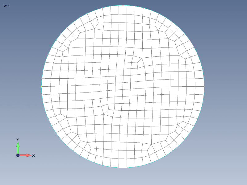
I have seen several examples, using either triangular elements only or a mix between triangular and rectangular:

mesh_kna5n8.png


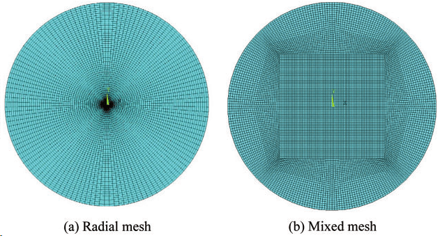
Why is best? Are there better alternatives?
 
Replies continue below

Recommended for you

I can see that the mesh was generated in Abaqus. You can use the Verify Mesh tool to check the quality of elements in both cases and/or (even better) run tests with different meshes for the considered scenario and compare the results.
 
IMHO, the radial mesh is way too concentrated at the center.
radial mesh can be QUADs (well, mostly).
if you do use TRIAs, be sure to use mid-side nodes (TRI6) ... TRI3s are terrible elements ... good only for being consigned to the center (and ignored).

what do the results for these (and other meshes) tell you (about the results) ?

"Hoffen wir mal, dass alles gut geht !"
General Paulus, Nov 1942, outside Stalingrad after the launch of Operation Uranus.
 
FEA way said:
I can see that the mesh was generated in Abaqus. You can use the Verify Mesh tool to check the quality of elements in both cases and/or (even better) run tests with different meshes for the considered scenario and compare the results.

rb1957 said:
IMHO, the radial mesh is way too concentrated at the center.
radial mesh can be QUADs (well, mostly).
if you do use TRIAs, be sure to use mid-side nodes (TRI6) ... TRI3s are terrible elements ... good only for being consigned to the center (and ignored).

what do the results for these (and other meshes) tell you (about the results) ?

It is an example picture, I havent started with the mesh yet.

Yes you are right, but Im looking for a general answer and to understand why.
 
general answer already given ... on one level, it doesn't matter. use whichever meshing "floats your boat".

For me a key consideration would be whatever (if any) stiffening elements are part of the design.

Mesh density comes down to what you think is (and/or can show) is reliable. Part of this is ...
1) what are you taking form the model? stresses ? loads (and then doing hand calcs) ?
2) How much testing will happen ? full scale ultimate test ? none ??

"Hoffen wir mal, dass alles gut geht !"
General Paulus, Nov 1942, outside Stalingrad after the launch of Operation Uranus.
 
Please show a figure if the loading, and the boundary conditions. Also indicate where you think the critical stress locations will be. (Not likely to be the center of the circle).

Also, what is the physical thing you are trying to model?
 
I can offer one additional mesh variant - unstructured mesh. In some cases unstructured mesh may produce elements with higher quality than structured meshes where large portion of elements must be skewed to produce structured pattern.
123_y9jsmv.png
 
@muruep00

1) You do not want to think of the mesh without any consideration for what the loading/BCs are and where the gradients of interest are located in the domain. As one good example, consider the following: To capture boundary layer gradients correctly in CFD, highly anisotropic elements are used near the boundary layer. Those same elements are awful for the main flow. Check out a few images if you haven't seen those meshes.

2) As you refine the elements, all meshes will degenerate so, I suppose, the real mathematical question is - which mesh topology has the slowest rate of "degeneration"? Its the one that is referred to as the butterfly topology. As far as I know, all other mesh topologies degenerate at a faster rate. But, again, that does not imply butterfly topology is the optimal choice in all cases.


*********************************************************
Are you new to this forum? If so, please read these FAQs:

 
For shells (4-noded), quadrilateral shapes produce the most accurate results. As you increase side lengths and start to attain acute angles (e.g., close to 180 degrees), the Jacobian (used for computation of integrals over the reference element, among other things) becomes ill-conditioned and the system of equations to be solved can become ill-conditioned, leading to an inaccurate solution.

The picture posted by karachun shows what seems to be a good mesh. Reducing the mesh size, but maintaining that topology, would probably produce numerically accurate results.
 
Dear Muruep00,
Also if you run FEMAP you can split the circular surface in four portions like the following picture:

2d-mesh-circle1_a3jy4z.png


Next simply use the MESHING TOOLBOX activating the MAPPED MESH option and you will arrive to the following 2-D quality mesh where the JACOBIAN check is well below of 0.6:

2d-mesh-circle2_fe752x.png


Best regards,
Blas.

PD
To learn more about 2-D meshing please visit my blog:

~~~~~~~~~~~~~~~~~~~~~~
Blas Molero Hidalgo
Ingeniero Industrial
Director

IBERISA
48004 BILBAO (SPAIN)
WEB: Blog de FEMAP & NX Nastran:
 
Status
Not open for further replies.
Back
Top