Eng-Tips is the largest engineering community on the Internet

Intelligent Work Forums for Engineering Professionals

  • Congratulations waross on being selected by the Tek-Tips community for having the most helpful posts in the forums last week. Way to Go!

Meshing a simple cuboid shape of soil

Status
Not open for further replies.

UWOVenky

Geotechnical
Apr 21, 2015
30
0
0
CA
Attached is the figure of a simple cuboid of soil which I want to mesh. I have been able to mesh this part successfully but by putting a question here my main aim is to reduce the number of elements without affecting the seed size at the centre. At the centre there are 3 circles which have a seed size 0.45. The innermost circle represents the contact area between foundation and soil. Note that foundation is not shown here. Since the stress is very high near edges, 2 more circles with the same seed size are drawn. I have created a partition for these 3 cylinders by cutting them at 10 m from the top. The reason for doing this is that the first 10 m have high stress concentrations and hence the seed size is kept small 0.45 and then for the rest of the height i.e. from 10 m to 40 m(total height of the model) it is increase from 0.45 to 4 (10 times approx). The part is seeded with size 10 on all other edges. By following this procedure, I am getting 130000 elements and therefore for every iteration it is taking around half an hour to 1 hour. I am not able to figure out which meshing and how partitioning must be done to reduce the no of elements?
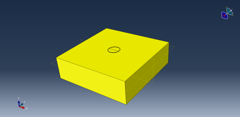
FullModel_upbajn.png


Kindly help.
 
Replies continue below

Recommended for you

Remember that the mesh quality is also important. I do not want to have lot of elements with face angle less than 35 or greater than 135 or aspect ratio greater than 10.
 
By symmetry are you saying that I must reduce the size of model to half? I can reduce the model to half the present size but after applying the X-symm boundary conditions on the exposed side of foundation and soil, the model does not seem to give right results. The sides are roller (U1=U2=0) and bottom is fixed for this 3 d model.
 
Depending on the loading, you could use quarter symmetry. The results should be exactly the same as a full model if you apply the correct symmetry restraints.

 
Quarter symmetry may give me doubtful results. I have a moment acting about Y axis besides a vertical displacement and horizontal displacement. Therefore I believe I should not use quarter symmetry. Is there a problem with uploading files? I have been trying to upload the .cae file from yesterday but it failed every time.
 
You are right, the file size is too large to upload. I am uploading another file. This time it is a circular foundation. It shows the way in which partitioning and seed sizes have been given. With this, I am getting 125300 elements. Can you have look at the file and edit it to reduce the no of elements? This file is in 6.10 version and if you are going to edit it in 6.13, then please share the pic of the your partitioned foundation. Thanks.
 
 http://files.engineering.com/getfile.aspx?folder=25bb814a-0355-4b86-aa5e-613f5ab59d41&file=VHM_Model-1.cae
As an alternative, you could also look into 'adaptive remeshing' using tets. Basically this will evolve the mesh based on the loading conditions. Start with a coarse mesh and let the convergence criteria add elements where needed. I hope this helps.

Thank you.

Rob Stupplebeen
OptimalDevice.com
My Personal WP
 
ok let me try that. But from my literature study, I understood that C3D8R would be better to use instead tetrahedral elements. And hence I have been using them.
 
Looking at the geometry there's not a lot you can do given the mesh density you've stipulated at the centre circle. You can tidy the mesh up by partitioning the circles and outer regions by using planes at 90 degrees to each other. But that's not going to significantly alter the number of elements you have.

 
ok alright, thanks for the support everybody. The reason why I have kept the seed size at the centre such small is I am trying to mobilize the full frictional resistance between soil and foundation. previously I was using a seed size of 0.95 but I could not get the favorable results. I checked all the other things to rectify the problem and found out no problem with them. So finally it gave me an idea that may be the interface does not have a fine mesh. And hence the present seed size! Do you have knowledge if I can use cohesive elements in the interface to model the contact between foundation and soil? I think that can reduce the mesh density.
 
In general bricks are more computationally efficient than tets and I would use second order tets if possible. For this case with adaptive remeshing you will be able to greatly reduce the element count which I expect will more than make up for the computational hit. I hope this helps.

Thank you.

Rob Stupplebeen
OptimalDevice.com
My Personal WP
 
Status
Not open for further replies.
Back
Top