Eng-Tips is the largest engineering community on the Internet

Intelligent Work Forums for Engineering Professionals

  • Congratulations waross on being selected by the Tek-Tips community for having the most helpful posts in the forums last week. Way to Go!

Meshing Octagonal Part- Face Angle less than 45 degrees

Status
Not open for further replies.

UWOVenky

Geotechnical
Apr 21, 2015
30
0
0
CA
Hi,
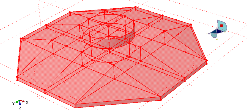
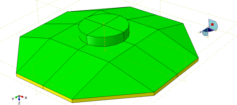
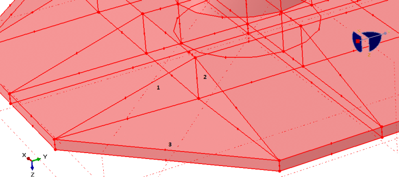
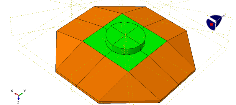
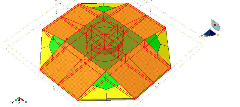
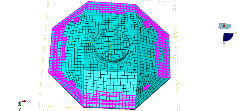
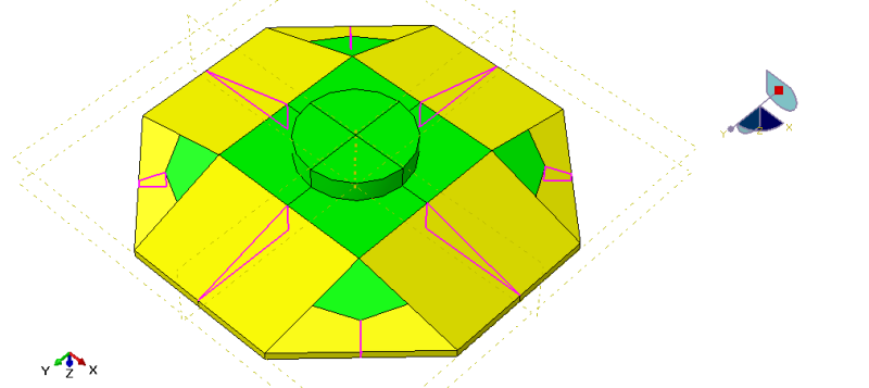
I am modeling an octagonal foundation in Abaqus. The foundation is 3.1 m in height. By its geometry, foundation has got slopes with face angle less than 45 degrees. As a result, when I mesh my model, I get a warning which says that distorted elements have been detected. This is around 25% of total no of elements. How can I partition/seed, etc. to reduce the no of distorted elements? I cannot compromise on the geometry of foundation. Attached is the mesh photo and distorted elements are highlighted.
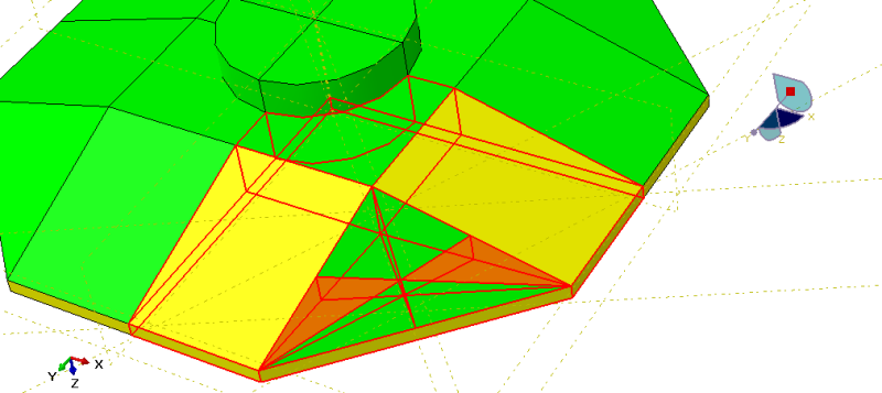
The four tetrahedron shapes at each of 4 corners are causing the problem. I tried bottom up meshing also but only in vain.
Please suggest. Thanks.

 
 http://files.engineering.com/getfile.aspx?folder=86b01d2c-d6d1-416b-8df7-2bd5fe8d0e7d&file=Octagonal_Foundation_Mesh.png
Replies continue below

Recommended for you

It appears that you've partitioned the lower slab across a plane so as to produce wedge shapes of a small angle. If this is to separate material regions isn't clear. However if these wedge shapes are required then there's not much you can do. In general though I'd start from the centre circle and partition that into 4 90 degree segments so you get structured regions there that use only quad elements. Work out from there so all the regions are structured regions.

 
The lower slab was created because I wanted a particular geometry of 3D octagon. The slab is partitioned only on the boundaries i.e. only faces have been partitioned but tetrahedron and lower slab are joined as one. Attached figure can throw some more light on this. The foundation has a single material-concrete throughout. If you are talking about the wedges at the base of the foundation, then it is not required. However, the tetrahedral shape i.e the slope of the foundations are required. The triangle constituting these tetrahedral shapes have face angles less than 45 degrees.
I am using C3D8R elements and C3D6 elements. More than 99% elements are C3D8R elements. I prefer using these elements because so far in my previous analyses I have got good results with these.
I will try using your suggested method of partitioning and see what happens. Thanks.

 
 http://files.engineering.com/getfile.aspx?folder=39f198f8-73a2-4cc3-83fd-ef6dc047b38b&file=Octagonal_Foundation_Part1.png
actually i checked again and the slab is partitioned not just on the faces but also inside. You were right. I tried remove the faces and combine the slab with the upper slopy part. However, Removing the wedges inside makes it unmeshable for swept or structured meshing. With bottom up mesh, I cannot mesh the part properly. the mesh protrudes outwards and does not fit the slopes exactly. Secondly, I also divided the part by starting at the centre of the circle and structured meshing do becomes available but it is still not changing the situation of distorted elements. Thanks.
 
Thank you Corus for that figure. I have got some questions in that. I partitioned the circle and swept it all the way down. Also I partitioned the body into 4 planes. But you have also mentioned "Partition this face and sweep down". I could not get which face is that? Are you mentioning the top outermost face with 4 edges or side inner face with 3 edges or something else. Secondly I removed the plane from all the 4 corners but this only makes that region unmeshable. Therefore, I created 3 datum planes and partitioned the tetrahedron at one of the corners. Fig 1 shows the model when tetrahedron is not partitioned using 3 datum planes and the plane has not been removed. With these partitions, Fig 2 shows the active meshing methods. The part is completely meshable but gives distorted elements.
Fig 3 shows the partitioned tetrahedron at one of the corners and the plane is also removed. However, some part of the tetrahedron is left unmeshable(orange color). May be this is not the way you suggested to partition. Can I send .cae file to you? If yes, how can I do it.
As you can understand from Fig 1 & Fig 3, I am able to do meshing but my main concern is distorted elements at the boundaries. Thanks.
Octagon_Fig1_ctvjzv.png

Fig 1
Octagon_Fig2_cxfdsn.png

Fig 2
Octagon_Fig3_rdifje.png

Fig 3
 
I partitioned the triangular face into 4 rectangular faces. You can either do that on the upper sloping face or on the flat underside face. It'd be better to then partition adjoining faces so that all regions stay structured regions.
Why you've left the plane that causes the wedge shapes in is a mystery. If you don't need that for material assignments, then remove it. All the problems of bad elements will then go. The only bad aspect of removing that plane is that the element shapes will taper down to the outer edge with a structured mesh. There's probably a way round that by defining the regions as swept.
You can attach the .cae file here but delete all the elements beforehand so as to reduce the file size.

 
Attached is the .cae file. I have removed the faces- the bottom triangular face, the right and left hand side triangular shapes from each of 4 tetrahedrons. However when I drag my cursor and draw a rectangular shape, you see the figure 1 given below. But the faces 1,2 and 3 have been removed by using Geometry Edit>Remove Faces. After removing faces, I am yet to partition the way you suggested in your last post. I will update you on that. In the mean time, here is the photo how the model looks after removing the faces in terms of meshable regions(fig 2).

Octagon_Fig4_m6b7hr.png

Fig 1
Octagon_Fig5_tmnkwm.png

Fig 2
Thanks.
 
I did the partitioning the way you said by dividing the triangle on the top face into 3 rectangles and then partitioning the cell by extruding these edges. Here is the fig 1 and 2. By doing this, only about 7% of the elements have face angles less than 45 degrees as compared to 25% previously (highlighted in fig 2). However, I receive a warning. "The highlighted regions represent interfaces between regions that, when meshed using the currently assigned techniques, will contain incompatible interfaces. Tie constraints will be generated across all incompatible interfaces. changing the meshing techniques will not solve the problem, but further partitioning may." Fig 3 shows the interfaces.
Octagon_Fig7_opkd9n.png

Fig 1
Octagon_Fig8_p1ouml.png

Fig 2
Octagon_Fig6_e0fbjo.png

Fig 3
Thanks.
 
I'm not sure what you're doing removing faces from a solid model and I'm still not sure why you just didn't remove the wedge partition that was causing all the problems in the first place. I took the cae model but that is in 6.10 and my version is 6.13 so sending it back to you would be a waste of time as you wouldn't be able to open a later version model.
All I did was to remove the feature that defined the wedge shape and then had to tidy up a few partitions as deleting anything in Abaqus seems to mess things up a bit. In the mesh module all the cells were structured regions. I used a mesh size of 0.25 rather than the 0.5 you used as this gives a better mesh size around the circular region inside the model. Note you'd have to reassign your material sections in the property module and also note that the section 'concrete' is missing.

When I did the mesh verification there was still some elements that would give warnings but there's not much you can do about that with the geometry and the elements didn't look that bad to me. Dividing the triangular regions up into 3 regions as you did wouldn't help either.
Attached are some pictures showing a wireframe of the partitions, and the final mesh.


 http://files.engineering.com/getfile.aspx?folder=c1a169d4-ed85-4a50-aa6c-36521ed98272&file=WireFrame.png
I was removing faces thinking that that is what you were referring me to do. Coming to the wedge partition, can you tell me which feature you removed to get rid of the wedges? I was thinking that removing a feature would change the geometry of the model.
Secondly, you can edit the file in 6.13 and send it to me. In my lab I have this version. On my laptop, however, I have 6.10. That will allow me to exactly see what you done. Thanks.
 
I removed partition cell 2,4,5,6,7,8,9,10 to get rid of wedges and the base square. Let me work from here and see what happens.
 
I was successful in removing the wedges by taking the partition cells off the geometry without affecting the shape of the octagon. With a seed size of 0.35 and partitioning in the form of triangle, I got warning for only 0.96% of elements. This is pretty good compared to my previous attempts. Thanks a lot for helping. Kudos to you!
 
Here's the cae file. The steps I took were to select 'delete feature' and to select the plane (using the mouse) that causes the wedge. That also deletes part of a partition across the circular region for some strange reason, so I repartitioned that using the plane already defined. After instancing the part in the assembly module, the instance is now made of all structured regions that can be meshed using brick elements. The triangular regions at the four corners cause some warning messages in the element shapes. In the cae file you'll see I partitioned one of the triangular regions into 4 segments as I explained earlier. This was done by sketching on the face and then extruding the edges through the cell. There's no particular logic to how the partitions were made. These were just based on what looked right. This partitioned region still has one or two elements that give warnings but there's not much you can do about that because of the geometry. In my opinion the warnings wouldn't be of concern. The final mesh could be improved by perhaps seeding some edges of the partitioned triangular region so that it looked more uniform but that's a matter of choice.

 
 http://files.engineering.com/getfile.aspx?folder=696f50b1-6d25-41a9-b8a2-70f152b2f456&file=Model_5-ChathamWTGFoundation.cae
As a postscript, if you redefine only the four corner triangular regions as swept regions with advanced front thingy, instead of structured regions, then you'll get no warning messages about element shape at all.

 
Status
Not open for further replies.
Back
Top