Eng-Tips is the largest engineering community on the Internet

Intelligent Work Forums for Engineering Professionals

Metal Building Tie Rod Modification 3

Status
Not open for further replies.

SteelPE

Structural
Mar 9, 2006
2,737
0
36
US
I have a client who owns a metal building which is currently being renovated. I was asked to work on a different portion of the project and made a visit to the site to assess conditions pertinent to the work that I was performing. While I was onsite, I had noticed that the client had demolished the existing slab on grade. I gave a stern warning to the owner regarding tie rods which fell on deaf ears.

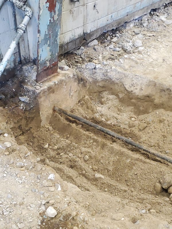
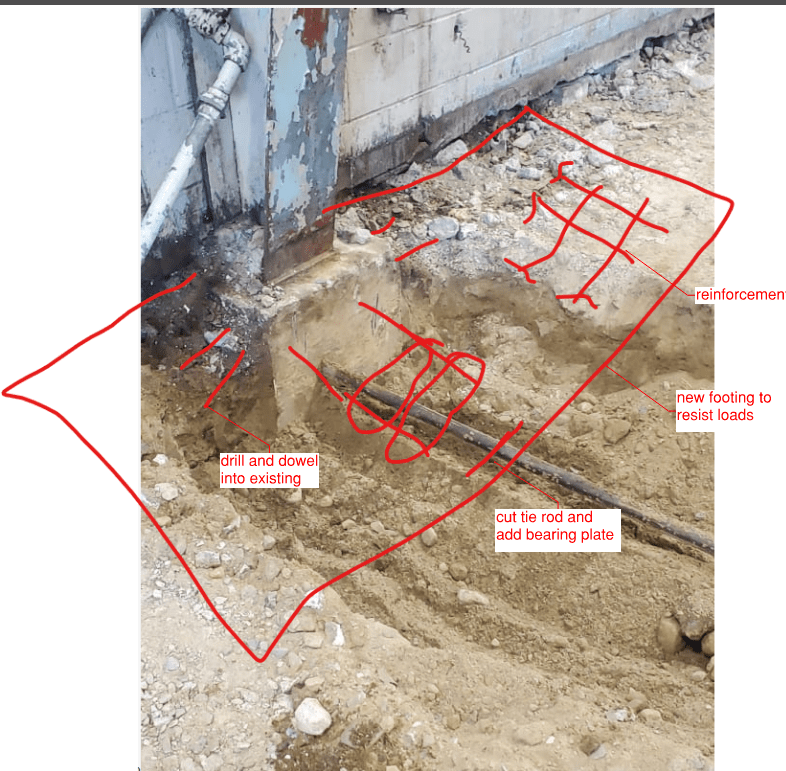
This week a received a call from the owner saying that while they were installing a trench drain in the middle of the building, they had the building tie rods and proceeded to rip them out (this is why we shouldn’t install tie rods people). Luckily, they only damaged the rods in the middle of the building so there is something at each end. I told the client that they needed to be repaired/replaced in like kind with new rods. The requesting an alternative solution which doesn’t interfere with their proposed trench drain (to save a nickel they are going to spend $100).

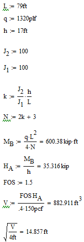
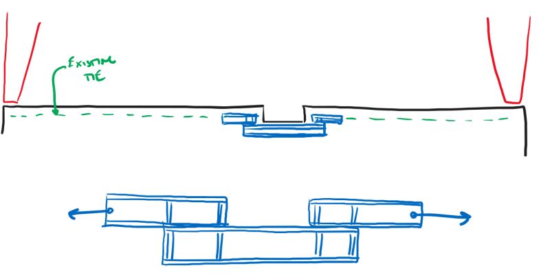
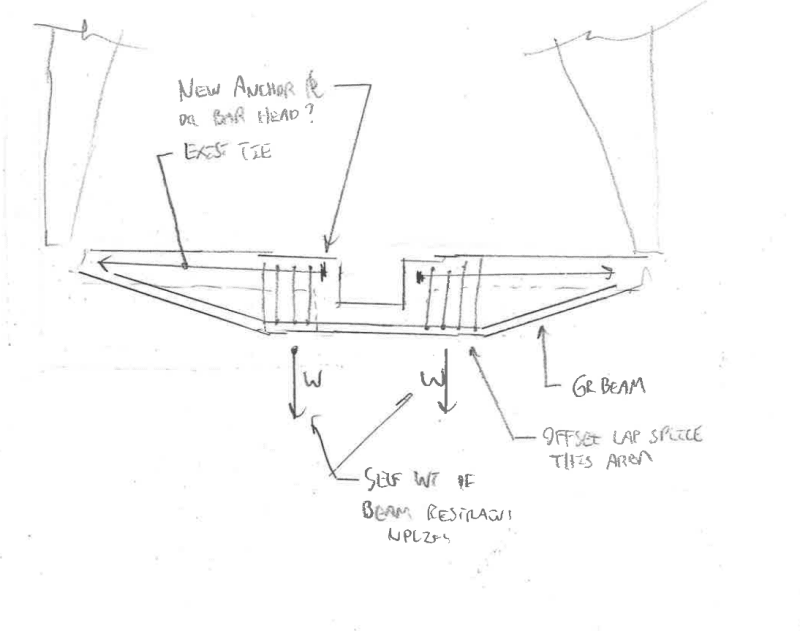
In the attached sketch you will find a proposed revised layout for the tie rods together with some back of the envelope calculations to figure the force in the tie rod (which comes out extremely close considering I am using a somewhat large DL). I don’t particularly care for making modifications to the rods, but don’t see any other way to accommodate the owners’ requirements. Has anyone made modifications to tie rods like this before?

Code = IBC 2015
 
 https://files.engineering.com/getfile.aspx?folder=5112f45f-a657-4200-9830-2ba6f0f61a0c&file=Frame_Configuration.pdf
Replies continue below

Recommended for you

Not sure I like it. Your details at the frame base connections may be difficult. Those tie rods are, conceivably, wrapped around the anchors and acting as edge reinforcement to prevent shear blowout at the slab edge (since MBS designers like to put the rods 3" from the edge of the slab). So your rods need to stay in that region and then come out and turn down. How do you deal with forces on the concrete and in the tie rod that come from trying to straighten out in that region? At the center it's not bad - you just anchor it with a massive chunk of concrete (which will probably be really big with those angles), but I think that the area near the frame base will be quite problematic.

How deep are the tie rods now? In the slab or were they cast in a trench below the slab? If it's below the slab, could they switch to a flat trench drain with periodic drains to a pipe? The pipe could be sloped below the ties while the trench is in the slab itself. (Could be a maintenance headache). Or they could pour a topping slab and keep everything above the structural slab.

Here's an idea...introduce a steel weldment that is capable of transfer the tension under the trench drain.

Screenshot_2022-05-13_101521_pnoujc.png
 
phamENG said:
How do you deal with forces on the concrete and in the tie rod that come from trying to straighten out in that region?

I agree that there will be a force opposite to the one that we are generating in the anchor. We plan on encasing the rod into a concrete section (say 1'-0" thick x 16" wide). This should help distribute this load back into the subgrade.

phamENG said:
At the center it's not bad - you just anchor it with a massive chunk of concrete (which will probably be really big with those angles), but I think that the area near the frame base will be quite problematic

Unless I am running the numbers wrong.... I am calculating the uplift force from each side to be 3.2 kips... So 6.4 kips uplift. Large, but not terrible (I have a metal building project with 100k net uplift at the base of the columns).... so a nice 6'x6'x3' footing would weigh 16.2 kips w/o including the overburden above.

phamENG said:
How deep are the tie rods now?

I don't know exactly at this point.... I am guessing they are about 8" to 1'-0" below the top of slab

phamENG said:
In the slab or were they cast in a trench below the slab?

They were placed below the slab without any concrete encasement (probably would have save us the headache if they had originally encased them in concrete)

phamENG said:
If it's below the slab, could they switch to a flat trench drain with periodic drains to a pipe?

Been down that road with the owner. They are so far refusing... hence the comment about spending $100 to save a nickel.
 
Are you in a heavy snow area? Once the rod was cut, the dead load redistributed somewhere and it is not likely to return once you mend the rod. That leaves the potential Roof Live or Snow load to contend with.
 
Ron247 said:
Are you in a heavy snow area? Once the rod was cut, the dead load redistributed somewhere and it is not likely to return once you mend the rod. That leaves the potential Roof Live or Snow load to contend with.

Pg = 40
Pf min = 35

I understand what you are getting at. I am not sure of the overall sequencing. I have used tie rods on occasion in the past, and since they are usually cast into the slab they are not set until the slab is poured.... which isn't until the building is erected and the roof is on (to protect the slab during the pout). In this instance the foundations should be supporting the DL of the structure. That might not be true here but I have no way of knowing.

I was thinking of installing coupling nuts on the system and them having them torque them the best that I can. That should be a bit of pretension in the system.
 
Clever ideas. This is kind of a blend of them. Maybe you could run a temporary, pretensioned turnbuckle system between the columns to draw them together while the tie is reconstituted.

While any tension in the rods has indeed been let go, chances are that any damage resulting from that has already occurred too. If there's no damage, great. If there's some damage, I guess that's already baked into the cake to a large degree.

C01_iovwis.png
 
GC Hopi said:
What about adding a footing for each column

I'm not sure if that would work or not. The only way I can figure a footing like that would work would be through concrete/soil friction... which would mean we would need a footing that had a weight of 150 kips to resist these loads (assuming a concrete/soil friction coefficient of 0.4). You may be able to gain some extra passive resistance, but I am not sure if the passive resistance is already being used by the system supporting the current dead loads.
 
winelandv said:
I think GC Hopi was suggesting a moment-resisting footing, but I could be wrong.

Maybe I am missing something, but doesn't a moment-resisting footing still need to resist lateral loads through a combination of soil friction/passive resistance?
 
We have gone the footing route before without much difficulty. Design the new foundation such that the combined sliding force and passive lateral resistance exceed the applied forces w/ applicable safety factors.

The deeper the footing profile... you'll get linearly increasing lateral passive resistance all the way up to whatever the geo-tech says is max. allowable. Avoids having to do gymnastics along the slab especially with whatever trench they are trying to get in there.

Inevitably, you'll end up designing this complicated tension transfer system and then the A/O will change the trench depth by 3" and you'll have to recalculate all your force-path angles/loads [dazed]
 
Forgive me if I'm wrong here, but doesn't the code require mechanical or welded splices for these tie rods? In this case, would it be possible to "drape" the tendons at very low slope under the drain? These tie rods are almost never installed completely straight and almost always sag in the trench they are cast in. While you may not be able to counteract the dead load at this point as it's most likely already shifted, you could at least with the new rods handle the live, wind and snow loading.
 
The horizontal translation of the foundation wall came from two sources - 1) retained soil, and 2) frame action. I think the former has little effect unless the fill configurations on both sides of the wall have changed and causing stress changes, then you should evaluate the strength of the beam-column joint given out to large rotation and result in movement of the column and its support. If the bent is stiff, the potential for the column's leg to move is close to none. However, this (analysis) is easy said than done, practically I probably will provide a deadman at a short distance from the wall, and utilize the passive earth pressure to resist the lateral load.
 
Aesur said:
Forgive me if I'm wrong here, but doesn't the code require mechanical or welded splices for these tie rods? In this case, would it be possible to "drape" the tendons at very low slope under the drain?

What is definitely prohibited in a tension tie is a conventional lap splice. I believe that a properly designed STM version of an offset lap splice is still street legal so long as there are explicit ties placed transversely. In my mind, prohibiting this would be akin to prohibiting permanent compression ties (the struts in the STM). And that would basically be akin to prohibiting columns. I think that the conventional lap splices are prohibited primarily because they rely on the tensile resistance of creeping concrete. If anybody knows otherwise, I would be grateful to hear of it.
 
SteelPE said:
Maybe I am missing something, but doesn't a moment-resisting footing still need to resist lateral loads through a combination of soil friction/passive resistance?

It does indeed. Frankly, I'm pretty skeptical of the efficacy of any post-installed rebar footing extension.

The other difficulty that you may encounter with a footing extension solution that abandons the tie is that:

1) The existing footing will probably need top steel somehow unless all of that can sensibly be placed in the extension which is a dubious proposition.

2) You will have changed the shear and moment fields on you pier. That's probably no big deal if you know how the pier was constructed. Otherwise, it's something of a conundrum.
 
You would need a large footing (15'x15'x4') if you dont consider the axial load from the building column, passive from the soil, and overburden. However if you do a detail analysis I think you will find a footing to be pretty reasonable. Consider that the building load adds to the spreading force but also adds vertical load to the footing which increases soil friction.
Screenshot_xveunr.png
 
SteelPE said:
Maybe I am missing something, but doesn't a moment-resisting footing still need to resist lateral loads through a combination of soil friction/passive resistance?

Sorry, in my head (always a dangerous place), I had assumed that you thought that the suggestion was only for dealing with the horiz. forces.

Yes, you are correct, the moment footing still needs to resist the lateral via friction and passive.
 
As Kootk noted you definitely need more information on the existing footing whether that be as-built drawing or a little move excavation in the field.
 
KootK said:
2) You will have changed the shear and moment fields on you pier. That's probably no big deal if you know how the pier was constructed. Otherwise, it's something of a conundrum.

As long as you'd be doing the footings anyhow, it probably wouldn't break to bank to also add a buttressing element for the pier if you're unable to evaluate it.
 
Status
Not open for further replies.
Back
Top