Continue to Site

Eng-Tips is the largest engineering community on the Internet

Intelligent Work Forums for Engineering Professionals

  • Congratulations KootK on being selected by the Eng-Tips community for having the most helpful posts in the forums last week. Way to Go!

Metal deck diaphragm shear transfer at ridge of a gable roof with open web steel joist.

Status
Not open for further replies.

Nate2017

Structural
Apr 20, 2015
10
Greetings to all.

I am currently designing a steel framed building with metal roof deck supported by open web steel joist. The roof has a gable profile. The steel joist is spaced at 10 ft and sitting on wide flange girders. Based on my quick calculation, the rollover strength is not enough to transfer the shear to the chord (wide flange girder) thus some forms of shear connector need to be employed.

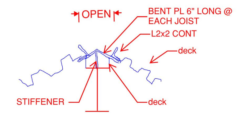
I came up with the attached detail. Basically, having a HSS shop weld to the top flange of the girder at certain spacing that matches the frequency of the sidelap fastener. And then having a wide bent plate welded to each side of the HSS. So the bent plates can catch the flute without worrying about the field alignment.

I have the following questions and thank you all taking time reading my post.

1. Will this detail work? If not, what will be your suggestions?
2. If goes by this detail, do you think the shear flow at the ridge in the diaphragm is disrupted or can I treat the windward and leeward diaphragm as a whole? I am leaning toward to treating them as a continuous diaphragm because the specified sidelap fastener is satisfied at the ridge.
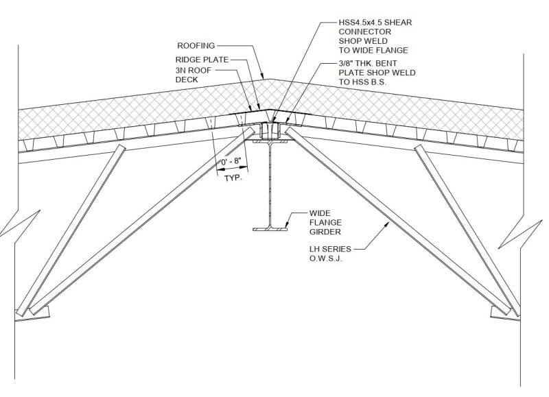
OWSJ_ridge_detail_ubkvxm.jpg
 
Replies continue below

Recommended for you

The detail seems excessive to me. There is no need for a continuous HSS above the WF. And there is no need for a continuous bent plate. Each joist shoe can be detailed to prevent rollover.

Shear flow at the ridge, in my opinion, will be unaffected by the angle change.


BA
 
Hi BAretired, thank you for your input. Please see my response in red.

The detail seems excessive to me. There is no need for a continuous HSS above the WF. And there is no need for a continuous bent plate. Each joist shoe can be detailed to prevent rollover.
Per "Designing with Vulcraft 3rd Edition" page 62, for large shear loads, or seismic loads, a shear transfer member, would likely be required between the deck and the Joist girder top chord, or edge beam.
I am thinking instead of welding a continuous HSS to the wide flange, s short piece matching the sidelap spacing should transfer the shear just fine.

Shear flow at the ridge, in my opinion, will be unaffected by the angle change.
What if roof deck sheet gets cut at the ridge line or there is a requirement for ridge vent? There is then no continuity in the decking. Also the shear strength of the diaphragm will be penalized with no sidelap fastener which is huge because the joist is spaced at 10 ft o.c.
 
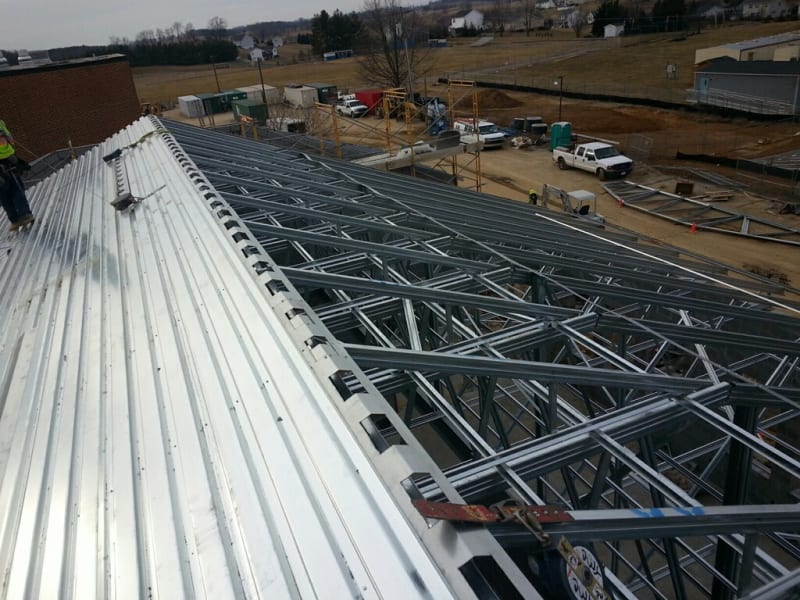
I’ve seen ridge plates with intermittent cutouts where ridge vents are required. For example:

2-6.8_e9sgoo.jpg
 
A couple of questions:

Is your ridge a collector? If not, and you use a ridge plate, then there's no load path for the shear load to go from the deck to the ridge beam and, thus, no rollover at the joist seat. If side laps are required, then you will need a ridge plate as you mentioned. Vulcraft/Verco and other manufacturers sell these a standard accessory piece with their deck. If side laps aren't required (after all, this will be the point of minimum shear in a rectangular, symmetrical roof), then you can just let the shear go through the joist. In that case, a nominal rollover load would be a good idea.

What if you split the diaphragm in half? Assume a break and look at it as two 3-sided diaphragms for wind along the ridge, and then for wind normal to the ridge look at your windward and leeward loads independently on each diaphragm. Does it work? If so, then the connection in the middle will be more about maintaining deflection compatibility than a significant load path.

bones - that's pretty neat. Is that your design? How did you analyze the plate for the openings?
 
If roll-over is prevented, can the steel stud be eliminated (don't know what it does, anyway) and can the angles be eliminated with the transfer strictly through the bent plate and the joist chord? Does the plate have to be bent? What are the magnitude of the shear forces? I've even seen intermittent 'struts/braces' located between joist seats to provide 'roll-over' protection.

Rather than think climate change and the corona virus as science, think of it as the wrath of God. Feel any better?

-Dik
 
pham - not my design, just something I came across while researching CFM truss suppliers. I’d probably just analyze the plate in terms of the net shear area.
 
Gotcha. I was thinking that, but the aspect ratio seems high enough to warrant an in-plane bending check. Though maybe the continuous bits would restrain it enough. Something to think about if I ever find myself with another gable roof with metal deck. I think I've only done two or three...most of my metal deck roofs are flat or a low mono.
 
Nate2017,

Is there some reason why you have selected a 10' spacing of joists? I have always found that the best economy is a 6' or perhaps even a 7' joist spacing in order to permit the use of 1.5" deep, 22 ga. steel deck, but you may have good reasons for your choice.

A doubly pitched roof diaphragm behaves like a folded plate rather than two separate diaphragms, but there needs to be a connection at the ridge so that the two halves of the diaphragm can act as one. I don't know the magnitude of shear stress in your diaphragm at the ridge line, but I suspect it could be handled without the HSS section. A bent cover plate could be provided across the ridge for continuity. That is shown on your sketch as "Ridge Plate". Is that not enough to resist the shear?

BA
 
I'd attach the ridge plate to the joists and not the deck...

Rather than think climate change and the corona virus as science, think of it as the wrath of God. Feel any better?

-Dik
 
Better attachment, I think and that's where you want the loads transferred to...

Rather than think climate change and the corona virus as science, think of it as the wrath of God. Feel any better?

-Dik
 
1) I've had some pretty bad experiences trying to get "special" rollover detailing on the joists seats and having the cost of the joists go nutso as a result. Maybe it's just the markets that I've been working in but if others have had success with that strategy, I'd be keen to hear about their experiences.

2) Mechanically, I think OP's details is super slick. But, of course, everything comes back to cost and, like BA said, this kind of detail tends to look "extreme" compared to what engineers typically, even if what engineers typically do is sometimes a bit questionable. You often see engineers make these details more economical but substituting gauge steel for the hot rolled stuff. That always raises questions about whether or not the gauge materail can survive construction traffic and fastening but, on balance, it seems to work out.

3) For lateral parallel to the ridge, you can sometimes take advantage of that being a low shear location in the roof deck. I find that usually does not help, however, owing to:

a) The rational need to consider some kind of unbalanced load on the diaphragm and;

b) Often the long direction of the diaphragm runs parallel to the ridge anyhow when a roof is detailed for economy rather than aesthetics.

4) I'm with phamENG on Bones206's pic of the shear plate: at those proportions, there would have to be some consideration of Vierendeel effects. That, or one just ignores the plate between slid bits and attempts to treat each solid bit as moment connected to the deck.

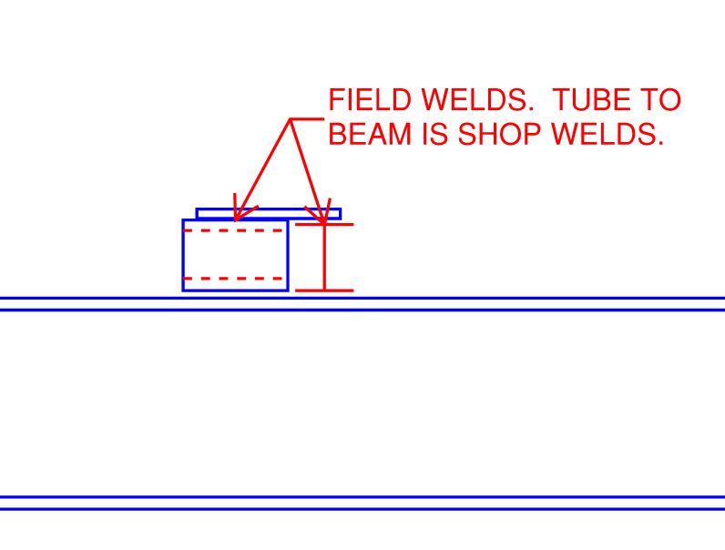
5) I've been half tempted to make my own joist seat rollover thingy and bypass the joist suppliers altogether. In doing something like this, though, one still needs to consider whether or not discrete shear connections spaced to match the joists is sufficient or if a continuous-ish drag element is still required. The detail below is for the trivial case of a flat roof but something similar could be worked up for a pitched roof.

C01_uojolf.jpg
 
I also wouldn't mind something like this although I'm sure that it would get VE'd out of every job, ever. You wouldn't even need to fasten anything to the joists.

C01_j7i4rs.jpg
 
KootK - at diaphragm chords I've done stuff like that. I usually have a continuous angle around the perimeter sitting on top of the joist seat, and the tube sits on the beam as shown with enough length to get enough weld to transfer the shear to the collector below (typically the beam, of course). The continuous angle is also welded to the tube on top, as the shear load is collected first in the angle.

But in this case...is the ridge beam a collector? Maybe it's just me, but that ridge beam doesn't look proportioned to take flexural loading from two spans of LH joists and a significant compression load. So it's probably not necessary here anyway...unless there's a bunch of braces in another detail we're not seeing. Probably just need to get the shear up and over the ridge and back down the other side.
 
The beam is labeled "wide flange girder", so it must be assumed that it carries the joists from both sides, possibly with columns appropriately spaced. The ridge plate is presumably gauge material and must be capable of transferring shear stress parallel to the ridge if adequately connected. There is no tendency for the joist shoes to roll over if the diaphragm is continuous across the full width of building.

If continuous ventilation is required along the ridge, that would have to be considered separately, as the continuity of the diaphragm would be interrupted. In that case, two diaphragms could be considered, one each side of the ridge, with a chord member each side of the vent opening.

BA
 
With respect to the OP’s detail, I think the HSS and 3/8” plates could be omitted, unless you are trying to create a more resilient system for high seismic or something. I think the bent plates would also require quite a bit of fabricator attention for coordination with the joist layout, which could create headaches.
 
phamENG said:
But in this case...is the ridge beam a collector?

It was never my intent to suggest that it was. That said, one still has collector-ish difficulties here with respect to how the shear in the deck is collected as a uniform thing and then, potentially, delivered discretely at the the joist seats. This goes away if one can take the deck shear across the ridge successfully without it ever really leaving the plane of the deck. But, then, you're back to having to deal with ridge venting issues etc. If cost were no issue at all, I absolutely would do something like OP or I have proposed. Mechanically, it makes all kinds of sense.

phamENG said:
Probably just need to get the shear up and over the ridge and back down the other side.

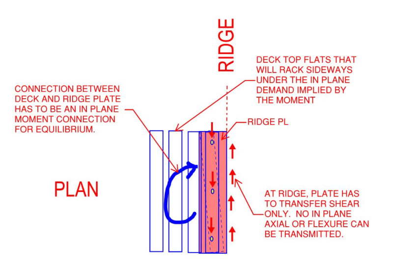
With my detail, it would be about getting the shear down and under the ridge and back up the other side. Capiche?
 
I do what everybody else does in these situations but, taking a critical look at the statics of the situation, I feel that there clearly are some things to dislike about the conventional approaches to shear transfer across the ridge. It's one of many, many things that I'd like to see some research on. But life, and structural engineering, must go on.

C01_tcxzgi.jpg
 
We did a similar project once where the fabricator choose to bend a plate at the bearing of the joists so that the joist seat itself was standard. The height of the beam had to be adjusted accordingly by the detailer.

Not an answer to the diaphragm question, but might have some bearing on the geometry.

 
Status
Not open for further replies.

Part and Inventory Search

Sponsor