Continue to Site

Eng-Tips is the largest engineering community on the Internet

Intelligent Work Forums for Engineering Professionals

  • Congratulations KootK on being selected by the Eng-Tips community for having the most helpful posts in the forums last week. Way to Go!

Metal deck diaphragm shear transfer at ridge of a gable roof with open web steel joist.

Status
Not open for further replies.

Nate2017

Structural
Apr 20, 2015
10
Greetings to all.

I am currently designing a steel framed building with metal roof deck supported by open web steel joist. The roof has a gable profile. The steel joist is spaced at 10 ft and sitting on wide flange girders. Based on my quick calculation, the rollover strength is not enough to transfer the shear to the chord (wide flange girder) thus some forms of shear connector need to be employed.

I came up with the attached detail. Basically, having a HSS shop weld to the top flange of the girder at certain spacing that matches the frequency of the sidelap fastener. And then having a wide bent plate welded to each side of the HSS. So the bent plates can catch the flute without worrying about the field alignment.

I have the following questions and thank you all taking time reading my post.

1. Will this detail work? If not, what will be your suggestions?
2. If goes by this detail, do you think the shear flow at the ridge in the diaphragm is disrupted or can I treat the windward and leeward diaphragm as a whole? I am leaning toward to treating them as a continuous diaphragm because the specified sidelap fastener is satisfied at the ridge.
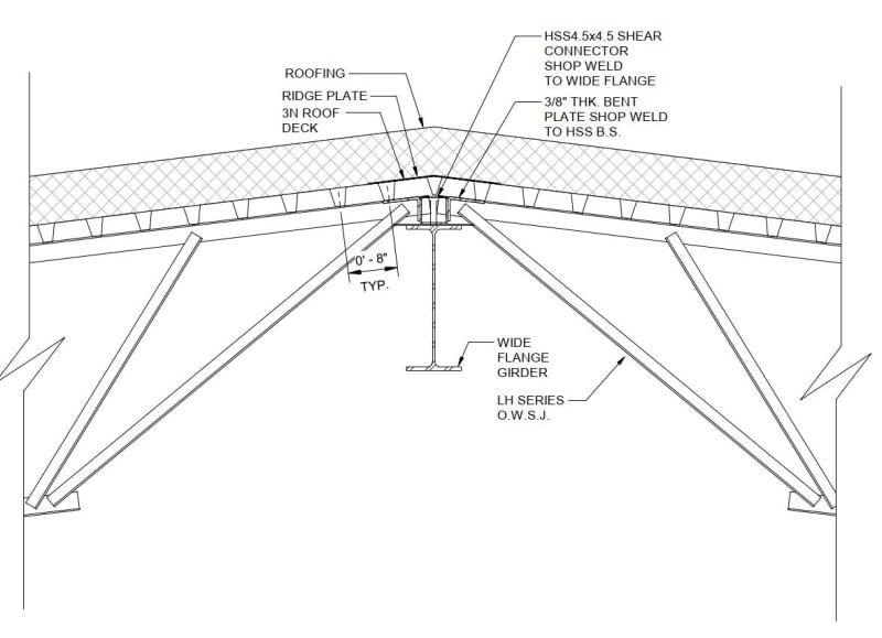
OWSJ_ridge_detail_ubkvxm.jpg
 
Replies continue below

Recommended for you

Kootk: is the roof panel not a pure shear panel?
It's too flexible to carry in-plane moments, which I think is what you're getting at in your diagram. It would be analogous to a post-buckled panel. Moments would be carried by end loads in the substructure.
 
KootK said:
1) I've had some pretty bad experiences trying to get "special" rollover detailing on the joists seats and having the cost of the joists go nutso as a result. Maybe it's just the markets that I've been working in but if others have had success with that strategy, I'd be keen to hear about their experiences.

If the roll-over loads get large enough, the manufacturer will be forced to put stiffeners in the joist seats. This prevents joist bundles from nesting nicely, and a truck-load of joists goes from an efficient full load to a low weight partial load quickly.
 
Ng2020 said:
Kootk: is the roof panel not a pure shear panel?

One would certainly like it to be a pure shear panel. Part of the argument that I've attempted to make here is that:

1) I'm not sure that's possible in this situation if one chooses to go over and across with a cap plate.

2) This may be a good reason to prefer more robust detailing at the ridge, at least from a mechanical perspective.

Ng2020 said:
It's too flexible to carry in-plane moments, which I think is what you're getting at in your diagram.

3) It's flexible but I'm not convinced that it's too flexible. A corrugated deck diaphragm is actually incapable of resisting pure shear without also engaging that cringey, flute racking behavior.

Ng2020 said:
Moments would be carried by end loads in the substructure.

4) I don't understand but I'd like to know more about this. Can you elaborate?

sbisteel said:
This prevents joist bundles from nesting nicely, and a truck-load of joists goes from an efficient full load to a low weight partial load quickly.

5) That knowledge is new and valuable to me, thanks for sharing it. It's a bit nuts that such a little stiffener could have such a big impact.

JNLJ said:
Not an answer to the diaphragm question, but might have some bearing on the geometry.

It certainly would be an answer if the more conventional seat height made rollover viable again.


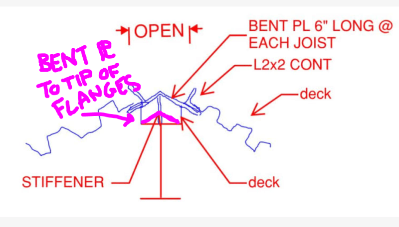
Sketch to clarify what I meant with the bent plate bearing.

Capture_fnofuw.png
 
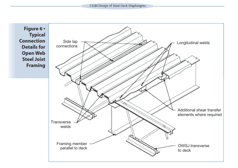
The section at the ridge does not differ significantly from the detail below, except in minor detail.

Venting does not need to be continuous for the full length of the ridge. Vent openings can be separated and the deck between vent openings must be adequate to resist the total shear.

image_ledfe8.png


BA
 
Kootk: I was thinking of the corrugated panel working similarly to a diagonal tension beam web, and the transverse joists acting as the beam caps. The former being buckled and or corrugated, and therefore very 'soft' in response to in-plane moments. The panel therefore carries almost pure shear and negligible in-plane bending. The transverse joists carry the in-plane moment as a couple of axial tensile / compressive loads (in addition to secondary bending effects due to web buckling).

 
Ng2020 said:
The transverse joists carry the in-plane moment as a couple of axial tensile / compressive loads (in addition to secondary bending effects due to web buckling).

I think that the tricks to that are:

1) The vertical separation between the cap plate and the joists. How do you get those tensile and compressive loads from the cap plate and down to the joists without passing then through the deck flutes?

2) I imagine there's some, upper limit to the length of cap plate that can be considered flexurally effective in this way. Maybe a 4:1 aspect ratio or limited by the practical lengths of individual segments.

 
I think we're over-complicating this. Why are we taking the diaphragm shear through the joist seats at the ridge? Is there a lateral force resisting system running along the ridge? In that case the HSS members would make sense to me, and they would be collectors.

I usually try to avoid a lateral force resisting system down the center of the building if I can. The diaphragm shear at the ridge (which is theoretically zero for a simple span symmetrical diaphragm) only needs to get from the deck on one side of the ridge to the deck on the other side of the ridge. A 1/4" continuous steel bent cap plate can take care of that without the HSS. The only rolling load in the joist seats would be from the ridge beam and supporting columns trying to pass their seismic loads up into the diaphragm. That would normally be a relatively small load.
 
I tend to agree that we are over-complicating the issue. The diaphragm shear force is normally zero at the ridge line, but with variable wind or seismic load, some shear could exist. Ridge line venting could decrease shear resistance, but this is easily handled in several different ways.

BA
 
I don't think I saw it mentioned above, but for lateral load in the transverse direction, isn't the shear that needs to be transferred across the ridge equal to the transverse shear at any point in the diaphragm? I find that to be the more critical condition with respect to demand at the ridge.

I typically detail this similar to the sketch JNLJ posted.
 
Deker said:
I don't think I saw it mentioned above, but for lateral load in the transverse direction, isn't the shear that needs to be transferred across the ridge equal to the transverse shear at any point in the diaphragm? I find that to be the more critical condition with respect to demand at the ridge.

Agreed, that what I was hinting at with this, somewhat ineffectively.

KootK said:
b) Often the long direction of the diaphragm runs parallel to the ridge anyhow when a roof is detailed for economy rather than aesthetics.

For load transverse to the ridge, a central ridge is actually the peak shear location within the depth of the diaphragm. It kinda depends on how much one buys into "pure shear panel" diaphragm behavior assumptions.

DCBII said:
Why are we taking the diaphragm shear through the joist seats at the ridge? Is there a lateral force resisting system running along the ridge?

It doesn't take a LRFS system at the ridge for this condition to arise and it's rarely the case that such an LRFS exists at the ridge. Rather, the detail represents one version of attempting to pass the diaphragm shear from one side of the ridge to the other.

DCBII said:
I think we're over-complicating this.

For my part, I've been "over-complicating" this on purpose because:

a) It's interesting.

b) I really do feel that, if one tested one of these over the top shear cap setups, it would perform poorly.

That said, and as I acknowledged previously, I'm using the same details that everybody else is and I am aware of no associated field issues. However, I feel pretty strongly at the same time that the cap plates are pretty worthless and that it's actually joist rollover getting the job done in these situations whether the joist supplier blesses it or not.

I've heard no reports of laterally pancaked joist seats. And that's probably good since such a pancaking would probably compromise the gravity load carrying capacity of the joists.

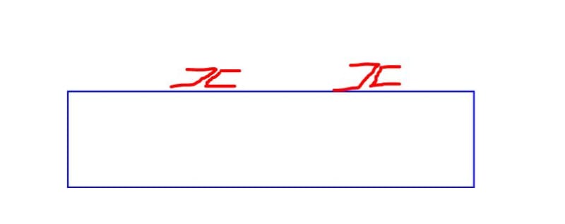
C01_vi7flm.jpg
 
Another thing to take into consideration with the proposed detail is that it could pose a significant safety hazard for the iron workers if they have to walk those girders with the intermittent shop welded HSS & plates in place.

 
Deker: The OP was concerned about rollover strength of the joists. For diaphragm shear perpendicular to the ridge, the shear is parallel to the joists, and there are no rolling forces. The HSS serves no purpose in either direction unless the deck is dropping diaphragm shear into a LFRS at the ridge line. It stays up in the diaphragm unless a stiffer load path is provided by a LFRS.
 
What is a LFRS? Found it! Lateral Force Resisting System. Everyone is talking in acronyms nowadays! I do not relate.

BA
 
DCBII: My interpretation of the OP is that they are trying to transfer diaphragm shear across the ridge without relying on the ridge plate in order to treat the diaphragm as a single continuous member for lateral load transverse to the ridge. Without the ridge plate involved in the load path, this shear transfer does need to occur via rollover, bent plate, HSS blocking, or some other means.

A few of the responses suggested that this isn't a huge issue because the ridge is a point of zero / low shear, but that isn't true. The shear transfer demand at the ridge will be dictated by the shear flow from lateral load transverse to the ridge. For conventional shear panel diaphragm theory, the magnitude of the shear flow will be equal to the transverse diaphragm shear.
 
Deker said:
A few of the responses suggested that this isn't a huge issue because the ridge is a point of zero / low shear, but that isn't true.

Guilty as charged! I keep thinking of shear as having one direction, but shear is numerically equal on sections at right angles to each other. So shear stress transverse to the ridge causes equal and opposite shear stress parallel to the ridge.

However, shear stress would tend to be lower at the midpoint of the ridge, so that may be a good location for roof vents. Ridge plates cannot be continuous where vents are located, but they could be continuous in the high shear areas beyond the vents.


BA
 
I did a, relatively, small building with high snow loads and some seismic. My situation was a bit different. The structure needed to transfer shear through dormers and valleys in each primary direction due to offset locations of moment frames.

My detail looked a lot like the OP’s. But, part of the reason for the valley connections was to pickup vertical loads in the unsupported decking edges. So, no one complained about the robust ridge detailing.

Maybe a shear only transfer bent plate could have worked at the ridge but I was concerned about the unsupported span over the large beams. We were using wide flange rafters that were in depth so there was a significant void.

That in mind, wouldn’t there be an out of plane force component (vertical) as the shear “climbed” over the ridge which could produce bending stresses that could be considerable if the gable pitch was high (mine was an 8:12). I doubt this would be a failure mode...but something to consider in the right circumstances.

 
Status
Not open for further replies.

Part and Inventory Search

Sponsor