Eng-Tips is the largest engineering community on the Internet

Intelligent Work Forums for Engineering Professionals

  • Congratulations waross on being selected by the Eng-Tips community for having the most helpful posts in the forums last week. Way to Go!

Metal Deck Slotted Connection

Status
Not open for further replies.

ChiEngr

Structural
Oct 19, 2021
69
US
Hello,

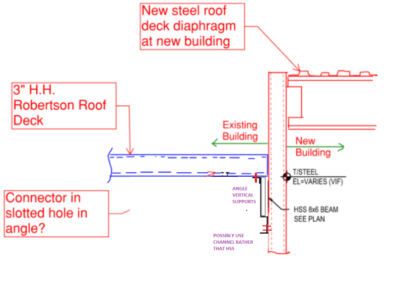
I have a really difficult connection to detail here, and I am about out of ideas. I am trying to resupport existing steel roof deck (H.H. Robertson Type DC) on a brand new collector beam at the interface of an existing building and new building expansion. I want the connection to be able to transfer in-plane shear loads, but not take any transverse shear loads that could potentially cross the interface via the new roof diaphragm at the new building. Does anybody have any ideas as to how this can be achieved? I was thinking about using 1/4" A307 bolts in slotted holes in the angle, but I have never seen bolts be used to connect light gauge deck to structural steel.
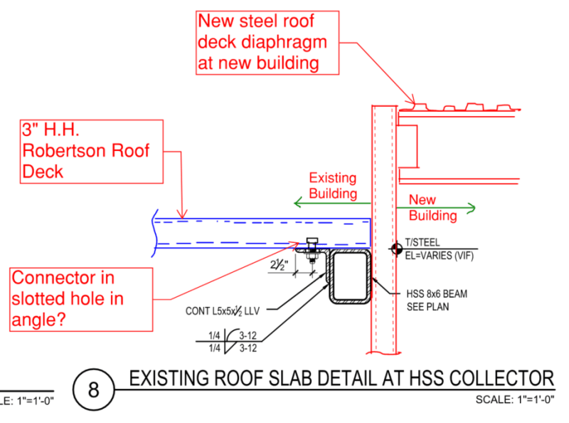
Connection_Detail_wjrmdh.png
 
Replies continue below

Recommended for you

I wouldn't try to make the slot at the angle to deck connection, I would rather make the thing that supports the angle to deck connection slotted. Basically try to move it downstream.
 
If you put a chord angle (heel pointing up) at the end of the EXISTING roof deck, would this not allow you to split the roof decks? You wouldn't have transverse shear trying to push into the higher diaphragm.
 
1) I'm of the opinion that any movement joint that relies on nothing more than slotted holes is junk that is likely to bind up for any number of reasons. This, even more so with cold formed steel than with hot rolled.

2) I suspect that any version of the detail that would do what you want reliably will wind up requiring teflon strips and all that jazz which would be prohibitively expensive.

3) I feel that your viable path here will be one of these options:

a) Separate the structures for all directions of lateral load.

b) Separate the structures for no directions of lateral load.

4) If you need to manage how much load goes where with the structures connected, I would explore do that by attempting to "tune" the relative stiffness of the adjacent structures.

If somebody can come up with a practical, unidirectional movement joint for this, I'll be the first to offer up kudos. It's tough, but not impossible, to build a better mouse trap.

Question: do you want the in plane shear from the deck transferred to the new structure? Or are the new and existing meant to slip past one another such that you only need to get the shear to the new collector? I'm not clear as to whether the new collector will be axially restrained by the existing building or the new one.
 
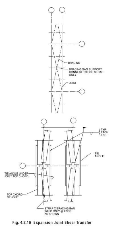
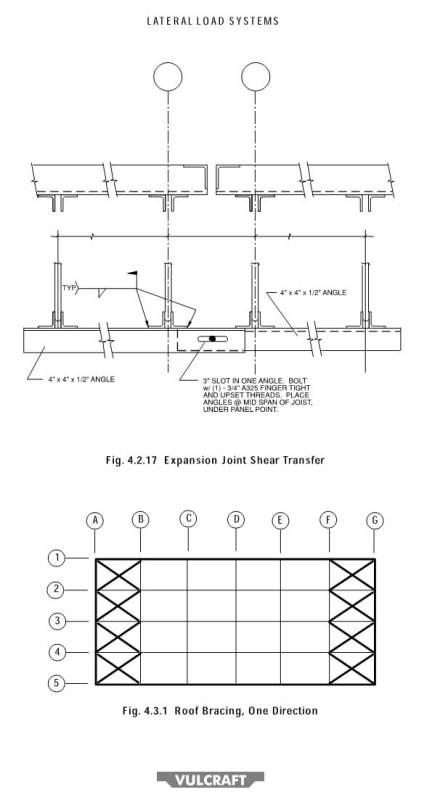
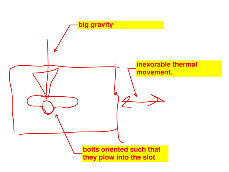
The nearest thing that comes to mind is this detail that's used in industrial buildings sometimes. It's not meant to transfer diaphragm shear in either direction. The angle with the slotted hole is just meant to iron out differential vertical deflection across the joint. In this instance, the slotted hole at least benefits from:

1) The slots are often in a dry, well ventilated, observable space and;

2) Thermal contraction forces can be monstrous so it's conceivable that those forces might overcome any binding in the slotted holes.

c01_cebp5c.jpg


c02_s0zsp6.jpg
 
Thanks for the responses everyone. I think I am going to go with a teflon slide bearing pad approach.
 
ChiEngr said:
I think I am going to go with a teflon slide bearing pad approach.

As I mentioned, that could get expensive.

Is it accurate to assume that your consideration of teflon means that your joints will be discrete and spaced out rather than continuous? If so, that may afford you some other, more attractive options.
 
KootK said:
1) I'm of the opinion that any movement joint that relies on nothing more than slotted holes is junk that is likely to bind up for any number of reasons.
Agreed. Though I must admit I do use slotted 'junk' connections regularly for minor connections and walkways. I'm regularly adding new buildings connected to existing buildings.

KootK said:
If somebody can come up with a practical, unidirectional movement joint for this, I'll be the first to offer up kudos. It's tough, but not impossible, to build a better mouse trap.

What I've done in the past is to provide sway supports that are braced in the orthogonal direction. It is fairly easy to create slender moment support or row of supports that have very little lateral stiffness. The actual connection can be bolted rigidly but if there is an intermediate support of low stiffness then the structures effectively become isolated in the desired direction. In this case you could lower the HSS 8x6 beam and provide moment connected risers of appropriate size up to the deck. Provide lateral bracing in the desired direction. For bonus points you can even open section rather than the 8x6 HSS. Thus you lose torsional stiffness and further reduce the stiffness. Of course by providing this much flexibility you have work a little harder to ensure there is no risk of axial or LTB along your load path.

temp_gcehjg.png
 
Thanks for the feedback Kootk and human909.

Unfortunately, I cannot drop the HSS beam. I really would like to use some type of slide bearing connection, but I understand that will be expensive. I don't have too much experience with a slide bearing connection so I will need to research this a bit more.

Do either of you have any experience using smaller diameter anchor bolts to fasten the deck to the steel? I am trying to read through some SDI publications in order to determine what limit states would be applicable? Definitely, the connector strength would not govern, but I am wondering if there is local bearing against the steel deck which would need to be assessed.
 
It appears you are connecting the HSS beam directly to the new building column. That is where I would provide the slotted connection, at the connection between the HSS beam and the new building column. Use some sort of seat connection that can allow movement left and right, but not in and out of the page.

Using slotted holes in roof deck or teflon for roof deck support are not options I would consider. Too unusual.

DaveAtkins
 
I agree with Dave and that's similar to what I said above, make the slotted connection between the steel members not at the deck interface.
 
I also agree with Dave's proposal. That's what I was getting at earlier with this comment:

KootK said:
Is it accurate to assume that your consideration of teflon means that your joints will be discrete and spaced out rather than continuous? If so, that may afford you some other, more attractive options.

Seriously, tell us more about the condition and what you want the joint to do and not do as far as load transfer, and we can probably offer a fair bit more help.

One thing to consider is that, if you allow the buildings to come together and move apart, you'll likely need to design your roof and wall envelope systems to accommodate that at the interface. That can be a bit of a hassle and, once you've gone that far, why not just a true isolation joint and be done with it?
 
@ChiEngr: this is the closest thing that I can think of to fit within your limitations. It won't win you any popularity contests I don't think.

c01_yjrklv.jpg
 
Kootk,

We are leaning towards doing something similar to what you suggested. I am working on the detail and will upload it here if you are curious. Definitely not winning a popularity contest.
 
I'm definitely curious. It's gracious (and brave) of you to consider sharing.
 
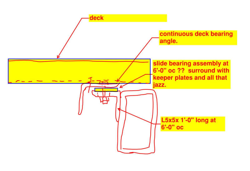
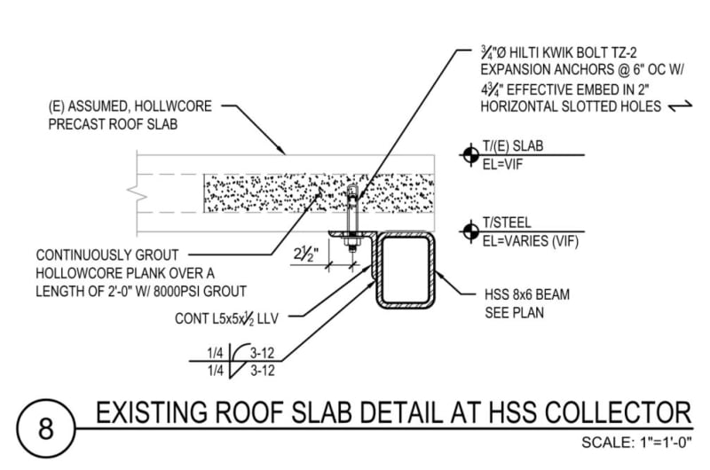
This building is extremely complicated. We are near the end of design, and we made an incorrect assumption (our fault) on the existing roof deck configuration due to lack of drawings. We assumed flexicore precast plank due to field observations, pictures, and the overall flat appearance of the soffit of the deck. Turns out during a recent site visit, we found an existing opening which lead to us determining it was actually a Robertson roof deck. We went from doing something as shown below (i know some don't like slotted holes), to now having to work out a slide bearing detail.

Capture5_f6jb3u.jpg


I appreciate all of the suggestions here; it is definitely a good learning experience for me for future projects. I am just kind of stuck with the system we have, so I am trying to work out a viable solution given the constraints.
 
Let me offer some addtional thoughts about slotted holes and teflon bearings. For this situation, where you are trying to separate two portions of a building with respect to lateral loads (wind or seismic), I think a slotted connection is adequate. I don't disagree with the comments above regarding slotted holes getting gummed up or not working properly, but I think it is standard engineering practice for this situation to use a slotted connection. I use a teflon bearing for a situation where you absolutely KNOW something will be moving, like a pipe outside that goes through large thermal cycles. I would not use teflon for something like this.

DaveAtkins
 
I agree. This is really the one that you want to watch out for. Article attached.

c01_rw5ee6.jpg


c02_b1h9ki.jpg
 
In practice, I usually either have a real separation joint or I hard connect things. I mostly consider slotted holes to be erection tolerance aids.
 
Status
Not open for further replies.

Part and Inventory Search

Sponsor

Back
Top