Continue to Site

Eng-Tips is the largest engineering community on the Internet

Intelligent Work Forums for Engineering Professionals

  • Congratulations MintJulep on being selected by the Eng-Tips community for having the most helpful posts in the forums last week. Way to Go!

metalography question 2

Status
Not open for further replies.

safaeng

Materials
Aug 29, 2010
9
Hello

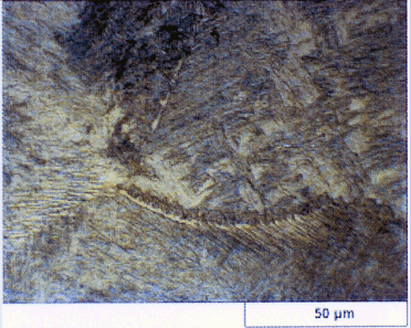
I am looking for some help on this picture (attached)

Ii is a resistance spot welded metal. Actually this picture is taken from the HAZ near to Weld metal.

The base metal structure is ferrite and pearlite and the chemical composition is :
C 0.15
Mn 1.02
Si 0.2
P, S, Al, Co, ~ 0.006
Mo 0.002
Cr 0.01
Cu 0.04

and the weld metal structure is martensite.
In this picture the steel is etched by 2% nital solution.

The laboratory told me the structure is ferrite grains with regions of pearlite, small particles of cementite and a little tempered martensite.

I know that the bright matrix is ferrite phase, can anyone tell me what part is pearlite or tempered martensite?
Do the laboratory told me the truth?

8-29-210.png
 
Replies continue below

Recommended for you

safaeng;
Sorry, but I can't tell from your attached micrograph. Do you have a higher magnification view? Did you have any microhardness testing performed?
 
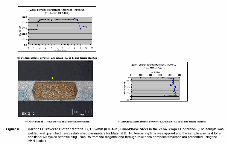
this is the micro-hardness profile of the weld. the line is the trace of micro-hardness measurement.


8-30-210.gif


and this is the best pic that I have got.
I know the resolution is low :( but this is all I have got.

110.jpg


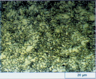
and this is the weld metal structure:

untitl10.gif
 
Honestly the micrographs are so poor I don't know how they can make a call. The last pic (weld metal) is better, and I can identify lath (Widmanstatten) ferrite from the prior austenite grain boundaries and probably bainite elsewhere. The hardness (for the chemistry given) certainly suggests bainite. But any self-respecting met lab should not need to refer to the hardness to identify carbon steel phases.
 
brimstoner;
thanks for your answer.

So you say that the WM (weld metal) structure is bainite and lath ferrite?

If so, Let me notice the process, the metal is heated to well above AC3 (austenite) temprature and is cooled at about 5000 'C per second.
As I know forming of bainitic structure needs less cooling rates and also time to be made. plus identifying bainite from martensite by nital etchante is not easy.
So, Is there any possibility that the weld structure be bainite and lath ferrite?
I think it is martensite and lathe ferrite.


and about the HAZ (first poor pic) What is your opinion about it in brief? any suggestion would be great.

Thanks :)
 
If this is indeed a resistance weld as you mentioned, you have highly localized heating and probably the highest cooling rate for any weld process.

With that said, and given the chemical composition of this steel, the weld region will simply be a re-cast structure of the original base metal composition. This means, the weld region should be ferrite/martensite with the expected cooling rate (look at a CCT diagram for this steel). The heat affected zone adjacent to the weld region will be a combination of ferrite and pearlite and possibly bainite/carbides. I don't see how you will have tempered martensite.
 
Well said metengr :)

I am far from an expert in this.
but indeed I can not see any reason to have tempered martensite there, neither.

I couldn't find any CCT or TTT diagram of this steel because it is a Japanese grade steel JIS SAPH 440. Hence as I don't know the temperature history at different spots of the weld, it is not helping much to determine the structure.

As another question, assume that we have spot weld, the HAZ structure is combination of ferrite matrix with areas of pearlite and cementite. Now assume that I re-weld it, but this time with lower current(say 50% of the first weld current). I expect that the HAZ with that structure, would be re-heated from 500 to 1000'C. What structure is expected there? Can we expect bainite/tempered marensite with ferrite?
 
safaeng
If you re-weld the same spot with 50% less current, the size of the weld region will be obviously smaller in comparison to the initial weld region. In this case, the second spot weld region will display the same microstructure as before, except the HAZ will now extend into the portion of the original resistance weld metal region resulting in some localized tempering of the original microstructure. I would run a weld coupon under these conditions and see what happens - micro and hardness testing.
 
metengr

Here is What you said:)

this is the one weld micro-hardness:

8-30-212.gif


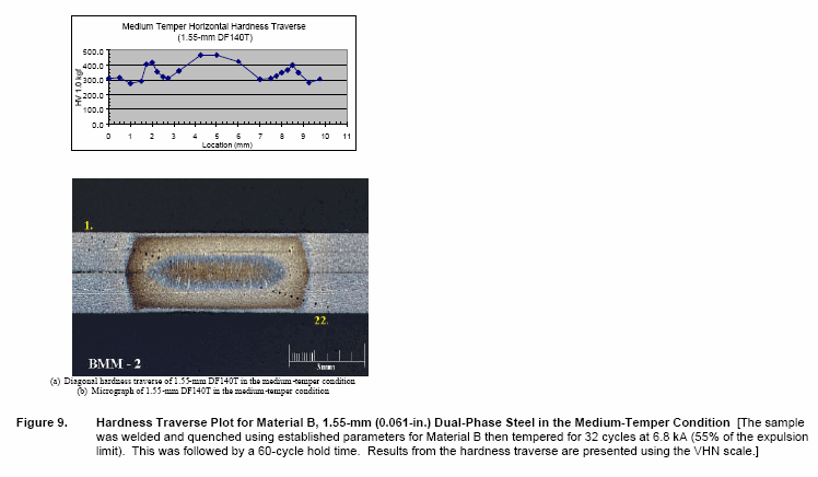
and this one is a re-weld:
actually it is a weld and temper schedule of weld
squeez-->weld1-->cooling by copper electrode--->weld2(50%)-->hold-->release

8-30-213.gif


as you see we have a tempered region just before the HAZ. But the HAZ is still hard.

There is a question: Is the New HAZ structure equal to the Original One?
 
Status
Not open for further replies.

Part and Inventory Search

Sponsor