Continue to Site

Eng-Tips is the largest engineering community on the Internet

Intelligent Work Forums for Engineering Professionals

  • Congratulations GregLocock on being selected by the Eng-Tips community for having the most helpful posts in the forums last week. Way to Go!

Meter-Out Flow Control Set Higher than Would-be Normal Flow

Status
Not open for further replies.

HydraulicsGuy

Mechanical
Feb 4, 2020
79
Please see the simplified hydraulic circuit below. Many components not shown for simplicity. For now, this is just a thinking exercise and not an actual situation.

Cylinder retracting. Gear pump putting out 10 GPM pump flow to rod end. 10 GPM is its absolute maximum flowrate at motor absolute maximum RPM. 1.5:1 cylinder ratio. That means flow from cap end would normally be 15 GPM. But pressure-compensated flow control is set to 16 GPM. Overrunning load acting on cylinder attempting to push fluid out of the cap end as cylinder retracts. What happens? I think flow from cap end would be 16 GPM. Pump is not able to fill up the rod end fast enough, which would require it putting out 16 GPM / 1.5 = 10.67 GPM. Pressure at rod end would drop to 0. Pressure at cap end is load-induced pressure. Cylinder retracts at a speed equivalent to 16 GPM. Am I thinking about this correctly?

This is a way to control the speed of the cylinder as it retracts with the overrunning load, while avoiding a pressure intensification situation. Any downsides? If the pump can't fill the rod end fast enough, is that a problem?
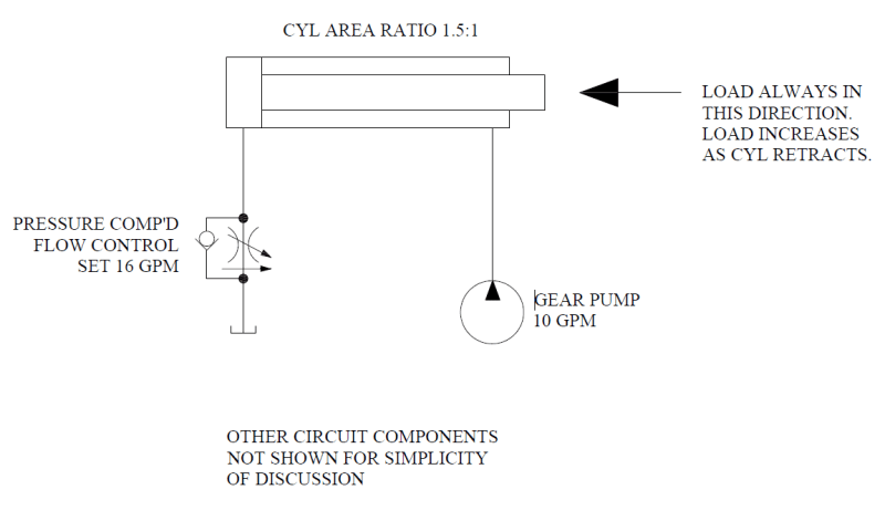
Eng-Tips_Question_jgf9wo.png
 
Replies continue below

Recommended for you

I think I have a pretty good feel for the situation. What I've learned is that putting a flow control that allows more than pump flow x cylinder ratio to flow from the cylinder is never a good way to go, due to potential for air to get into the system, or for cavitation to occur once that end of the cylinder is pressurized again.

I had seen an existing hydraulic circuit where there was a flow control positioned like I have in the original sketch, which would have led to a pressure intensification situation if set below 15 GPM. I was wondering why the designer did this. So I thought, 'maybe the plan was to set the flow control to more than 15 GPM to avoid the pressure intensification'. So I began to ponder what would happen if the flow control were set to greater than 15 GPM. Now I know what could happen (air ingress, cavitation once re-pressurized). The moral of this story is this I think: "avoid having a pressure-compensated flow control for meter-out when the external load on the cylinder is overrunning". If set too low, you get pressure intensification. If set too high, you get air ingress and cavitation.

Thanks to all who responded, thanks for the discussion.
 
How do you get pressure intensification when the piston is retracting? The system was capable of providing pressure required to extend against the same prevailing load that is returning the piston. You may have flow differences, extend verses retract. As the piston retracts the cap end pressure must be less than that pressure required to extend with the same load. Otherwise the load will not cause the piston to retract without rodend pressure.

Ted
 
If you have a gravity-overhauling load - e.g. turn your diagram 90 degrees anticlockwise and have the cylinder carry some sort of fixed load - then there is a special valve you can use on the bottom of the cylinder to avoid the situation that you are fretting about. That valve is called ... a "counterbalance valve".

Functionally, it's like a pressure relief valve with a check-valve allowing free flow in the other direction.

The idea is that you set the pressure on this counterbalance valve high enough so that the pressure on the top of the cylinder never drops below zero based on the pressure underneath the piston supporting the load.

They're not particularly fussy about that pressure setting matching the instantaneous load. As long as the setting is "more than enough", it will work. Obviously an excessively high setting of the counterbalance valve will make the machine stop working.
 
How do you get pressure intensification when the piston is retracting?

If flow control is set to 14 GPM out of cylinder cap end, pump flow into cylinder rod end will be less than 10 GPM on a 1.5:1 cylinder. That means some pump flow is dumping over relief valve. That means pump and rod end pressure go to relief valve setting. With a load pushing against the cylinder, the load and the rod end pressure together create intensified pressure on the cap end.
 
If you have a gravity-overhauling load - e.g. turn your diagram 90 degrees anticlockwise and have the cylinder carry some sort of fixed load - then there is a special valve you can use on the bottom of the cylinder to avoid the situation that you are fretting about. That valve is called ... a "counterbalance valve".

Functionally, it's like a pressure relief valve with a check-valve allowing free flow in the other direction.

The idea is that you set the pressure on this counterbalance valve high enough so that the pressure on the top of the cylinder never drops below zero based on the pressure underneath the piston supporting the load.

They're not particularly fussy about that pressure setting matching the instantaneous load. As long as the setting is "more than enough", it will work. Obviously an excessively high setting of the counterbalance valve will make the machine stop working.

Please read my post above yours. I’m not asking how to make this work.
 
Ok, I understand you thinking. I was thinking in terms of past experience designing a pressure intensifier where pressure on the large area creates higher, intensified pressure on the smaller area.

Ted
 
Status
Not open for further replies.

Part and Inventory Search

Sponsor