Continue to Site

Eng-Tips is the largest engineering community on the Internet

Intelligent Work Forums for Engineering Professionals

  • Congratulations KootK on being selected by the Eng-Tips community for having the most helpful posts in the forums last week. Way to Go!

Methods to laterally brace a cantilevered steel pipe column? 1

Status
Not open for further replies.

structure567

Civil/Environmental
Nov 12, 2013
50
I have an 11' existing cantilevered pole that is embedded onto the ground. I would like to brace the column somehow and was wondering if there are any ways to laterally brace a pipe column at the mid height. Will it be possible to install a seismic clamp and attach a high strength rod? The pole does have a 5'x5' sign that is attached at the top and is located at an open field where wind force will govern.
 
Replies continue below

Recommended for you

BridgeSmith said:
I understood the pole was embedded in (cast into) the foundation. Is that not the case?
yes, the footing is embedded about 5' into the ground and I have designed it as an unrestrained condition.
@retired13 I was planning on adding a pad type footing that is 18" deep around the existing foundation and connect it with rebars and epoxy.
 
structure567,

Yes, I understand. You should throw some number (moment capacity required for balance) on the pad, then you will find the fun part. Give it a shot, and let's know how confident you are :)
 
...the footing is embedded about 5' into the ground and I have designed it as an unrestrained condition.

That may be reasonable, or ridiculously conservative, depending on the frost heave potential at the site, and the diameter (or width) of the foundation.

Rod Smith, P.E., The artist formerly known as HotRod10
 
Rod,

OP said:
he existing foundation does not meet the required depth in order to resist the horizontal load. Please ignore the sketch of the new foundation. I have drafted this model just to show the conditions visually.
 
I saw that, retired13, but if the OP is ignoring lateral resistance, which is what I understood from the statement that it was "designed it as an unrestrained condition.", then there may be a lot of moment resistance that's being ignored. If I misunderstood, then I ask the OP to please clarify.

Rod Smith, P.E., The artist formerly known as HotRod10
 
BridgeSmith - the IBC provisions have two equations: restrained and unrestrained. Restrains means there's some sort of bracing at ground level - a large slab, for instance. That equation assumes that brace point in the overturning resistance and results in a smaller foundation. Unrestrained assumes you're in virgin soil in the middle of a field relying on nothing but that soil to resist overturning.

I'm assuming that's what the OP means.
 
Ah, thank you phamENG! The AASHTO provisions don't use that terminology, so I was a bit confused.

So, the question I would be interested in is, if it was restrained (by say a larger pad), would it be adequate per the IBC? I would be somewhat concerned with pouring a larger footing around the existing foundation, and considering it as a spread footing. Even with the dowels drilled in, moment transfer between the existing foundation and the surrounding pad may not happen effectively. If it's adequate in the restrained condition, doweling rebar into the existing would seem unnecessary.

Rod Smith, P.E., The artist formerly known as HotRod10
 
Rod,

Pile with pile cap, and/or pile installed beneath rigid mat foundation, can be considered restrained for lateral movement, if passive pressure can develop.

I guess the OP has designed the pier correctly without restrain on the pier head, since there was no intention to provide cap or pad at the time of design. However, mistake occurred during construction, thus the need to make up the deficit strength. Now, that's the fun part to design the "restrain" to assist the pre-installed pile to resist the lateral load effects - the portion of shared load, the connection, the soil pressures ..can be quite confusing, and highly uncertain. I think you got it.
 
I've found that the amount of passive pressure that needs to be developed to consider these pole footings 'restrained' is prohibitive and I'm better off using overturning of the mat footing. But that brings up the connection issues noted previously.
 
I still wonder if the less expensive option is to yank the whole thing out, dig the hole bigger or deeper, if necessary, drop a new pole in, pour a couple yards of concrete, and walk away.

I'm inferring from this other thread by the OP that the pole is also inadequate, unless that's a different project.

Rod Smith, P.E., The artist formerly known as HotRod10
 
structure567,

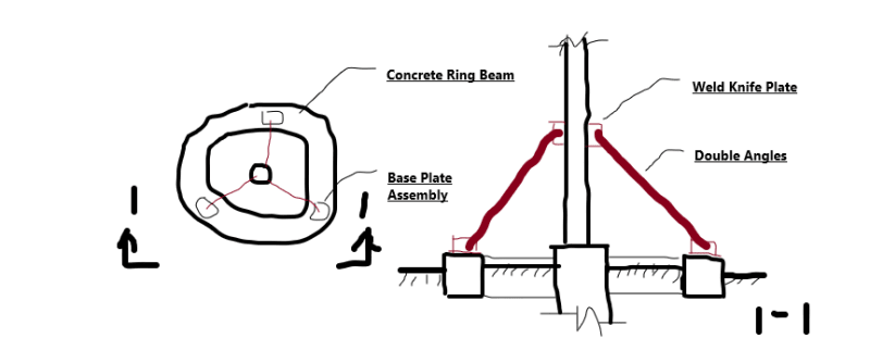
If you can back check, or estimate, the deficit in capacity, here is an idea for your consideration. Note that the angles to plate connections shall have slotted hole at one end to allow some movement of the pole, and allow the relief of tension in the angles. Once the bolts are engaged (in compression), and the angles start to deflect, the pier will then kick in to resist the remaining force.

Support_pk2msm.png
 
You might need to also consider torsional resonance of the sign in wind.
 
Improve soil under the new footing, or bring footing down to frost line. For small load, single angle might work too.
 
If this pole footing is defective in resisting horizontal load, then the retrofit should have at least 3 ties

Why? Curious as to the code you are referencing.
 
Whoop,

The "code" was brought up by my miss-read of the OP's statement - "The existing design does not meet load requirements." I took "load" as "code".

See my sketch posted on 3 Mar 20 18:46 you'll understand why 3 ties. The suggestion was based on engineering consideration, not a direct quote of the code. But does not the code require a capable and stable load resisting system?


thank you to everyone who replied.
I decided to go with retired 13 and STrctPono's advice of using cables and turnbuckles. I plan to have a minimum of 2 braces.
For retired 13, I see that in your sketch you drew a weld knife plate as a connector. Is that connection possible with a circular pipe post?
I'm trying tosee what is the best way to connect the cable onto the pipe column...
 
structure567,

Yes, it is a simple shear connection, connected to the pipe by fillet weld, if the pipe is weldable.
 
Can anybody point me to the right direction on how to design foundations for bracing through gable wires? Are there any codes or guides I should follow?
I have only accounted for uplift force created by the tension force through the wires but I'm sure there is more to account for.
 
Guy wire/cable system is commonly used in electrical pole, and communication tower type structures. Suggest to look into utility industry for guidance on design.
 
Status
Not open for further replies.

Part and Inventory Search

Sponsor