Eng-Tips is the largest engineering community on the Internet

Intelligent Work Forums for Engineering Professionals

  • Congratulations waross on being selected by the Tek-Tips community for having the most helpful posts in the forums last week. Way to Go!

Miami Pedestrian Bridge, Part II 55

Status
Not open for further replies.

hokie66

Structural
Jul 19, 2006
22,581
0
0
AU
Site management has requested that we limit the length of the other thread by forming a new one. This subject may require III, IV....

Link to Part 1
 
BARetired said:
The end diagonal, column and canopy slab still seem to form a triangle after collapse, although the connection between the end diagonal and column cannot be seen.

That triangle is the remaining parts of the members. The initial triangle is bigger.
 
hoikie66 said:
All the photos show me that the failure was a joint failure rather that a member failure. Both ends of Member 10 developed hinges at the same time.

Can you points out these hinges in #10? #10 appears intact and aligned with its nodes until after collapse from what I can see. #11 deforms and loses alignment with the top node from the outset of collapse. My money is on the top of #11.
 
For the benefit of PART II of this discussion, and so we are all talking about the same member #'s, here is a reference graphic:

Capturemiami_wno3we.png
 
It should be interesting to know where the cracking occurred.

Dik
 
When bridge consultants design cable stayed bridges for state DOTs...typically there are scale models of the bridge constructed...where the structure is put in a wind tunnel and wind analysis is performed...(you can't look up in ASCE-7 and get wind loads on something like this...I wonder if a scale model of the bridge was created (maybe at FIU?)..not only for the wind loads in Miami...but also for testing of the gravity loads... As Hokie has stated from the beginning of this thread (as he knows his stuff!) a concrete truss was a bad idea...I had never even heard of a concrete truss until this hit the news...I don't think I've ever seen one in person.
 
I think this really opens up a can for State DOT's as well...I would say in most of the US, that pedestrian bridges are not designed by bridge engineers, but are designed by building engineers (or at least in my state). A client (hospital or school) will hire a building engineer and the building engineer submits plans to have a bridge over a DOTs right-of-way to the state. Typically, there is no secondary check from a different consultant required as there was in this case (I'm guessing that was required because federal funds were involved).

But from a liability perspective, if a state DOT looks at the plans prepared by the consultant, how much liability does he take on? Even though the state DOT is not likely not an expert in the structure being designed (and most bridge engineers aren't even familiar with ASCE 7 loading)...if a State DOT PE reviews the plans and then approves it...IMO he is taking on some liability with the structure.

Sorry...bit of a tangent :)
 
Tomfh,

I don't really know which node failed first. They were probably all failing. But in the dashcam video, both the top and bottom chord hinged at the ends of member 10.
 
Structuralengr89 said:
.IMO he is taking on some liability with the structure.

Not a tangent, but, the next phase... I'm surprised a lawsuit has not already been filed.

Moreso in the US, than in other parts of the world, the lawyer will use a 'scattergun' approach and name all parties. If the lawyer misses one that he should have included, he can be sued.

FDOT, the city, the University, the consultants, the constructor, and any of the sub-trades are fair targets...

Dik
 
Hokie said:
But in the dashcam video, both the top and bottom chord hinged at the ends of member 10.

I couldn't tell if the failure was at the ends of the member or at the panel point the members framed in to. Could you?

Dik
 
dik said:
FDOT, the city, the University, the consultants, the constructor, and any of the sub-trades are fair targets...

Well, targets certainly; 'fair' is debatable. Probably include the concrete testing lab, special inspectors, material suppliers, etc, to the list too.
 
Just my opinion, but I think the truss was doomed to fail at the joints. At some stage, I hope we see some further information about the details, not just how the PT was arranged and anchored, but what was supposed to reinforce the joints. Based on the reporting which the NTSB released after the I35W collapse, we will eventually find out. It is ironic that Figg was the designer of the I35W bridge replacement.
 
hokie66 said:
They were probably all failing. But in the dashcam video, both the top and bottom chord hinged at the ends of member 10.

Can you post a screen grab of the phenomena you are talking about?
 
dik said:
I'm surprised a lawsuit has not already been filed.

The insurers would all be notified already, and are no doubt working out their respective positions regarding the inevitable claims.
 
Hokie said:
Just my opinion, but I think the truss was doomed to fail at the joints. At some stage, I hope we see some further information about the details, not just how the PT was arranged and anchored, but what was supposed to reinforce the joints.

Just realised that I couldn't find any reference to confinement reinforcing in the anchorage zones... those high compressive loads from the post-tensioning would give rise to some high tensile stresses in the vicinity of the anchor.

Dik
 
dik said:
Just realised that I couldn't find any reference to confinement reinforcing in the anchorage zones... those high compressive loads from the post-tensioning would give rise to some high tensile stresses in the vicinity of the anchor.

Yes the stresses would be fairly intense. The node region would be working real hard. I was wondering if the temporary rod was acting as confinement in some way, and when it broke or was released it led to the overall rupture.
 
hokie66 said:
I don't really know which node failed first. They were probably all failing. But in the dashcam video, both the top and bottom chord hinged at the ends of member 10.

hokie66....I agree that hinges formed but it looks like those occurred first at the top of members 11/10, then at the bottom of 11 and then at the bottom of 10. But....sometimes hard to tell failure sequence in progressive collapses.

My best guess, and I assure you that's all it is, is that there was buckling or punching shear at the top of 11, rotational failure at the bottom of 11, then tension failure at the bottom of 10.

Issues such at these usually get solved by the numerous ideas posed in such conversation as we are all having. Hopefully these discussions will lead to someone reaching a logical conclusion of the failure, but as a group we don't have the benefit of the cumulative information from design and construction that will inevitably be forthcoming...either through determined analysis or the litigation process. The resolution of such failures is important to the future success of innovative design and construction, it's just unfortunate that such a high price had to be paid for this lesson.
 
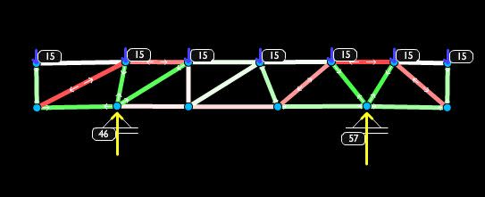
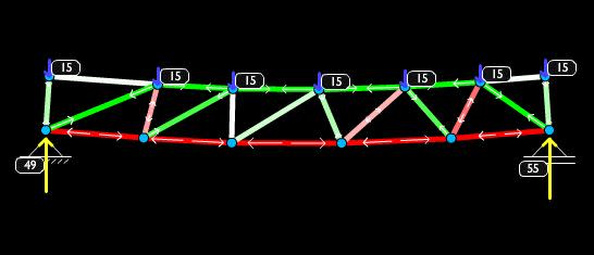
Just in case anyone is interested in a rough idea of the tension / compression loading of the trusses when:
A-In transit supported underneath in 2 places mid span
B-In Situ supported at either end of the span

These are not to scale or necessarily accurate, but give a general idea. Draw your own conclusions here.

transport_op5mdy.jpg


insitu_iec86z.jpg
 
Ingenuity said:
Well, targets certainly; 'fair' is debatable. Probably include the concrete testing lab, special inspectors, material suppliers, etc, to the list too.

Concur... had lumped the others under sub-contractors... Wonder if VSL were involved with stressing the cables... They've been involved with post-tensioning for decades that I'm aware of, and are very good...

tomfh said:
The insurers would all be notified already, and are no doubt working out their respective positions regarding the inevitable claims.

Shortly after it hit the ground...

Dik
 
Member 11 may have been a tension member during construction but it was a compression member after the temporary supports were removed. Assuming a total weight of 950 tons, the bridge reaction at each end would have been in the order of 950 kips under dead load only. Member 11 appears to be oriented at about 35[sup]o[/sup] to the horizontal, so it would have been loaded to about 1650 kips, a compressive stress of 3,300 psi on a 24" x 21" section under dead load only. It did not need any prestress at that stage.

BA
 
Status
Not open for further replies.
Back
Top