Eng-Tips is the largest engineering community on the Internet

Intelligent Work Forums for Engineering Professionals

  • Congratulations waross on being selected by the Tek-Tips community for having the most helpful posts in the forums last week. Way to Go!

Miami Pedestrian Bridge, Part II 55

Status
Not open for further replies.
dik said:
If it were acting in compression, it would be aggravating the problem, I would think.

What I meant was, maybe that additional compressive load was stopping it from failing in some other way, as opposed to a compressive failure. There would be tensile stresses trying to leak out in all directions...
 
Lnewqban said:
It seems to me that the I-beam shape of the bridge made it especially vulnerable to twisting loads and deformations, which could deteriorate the nodes of the web.

Agree. The truss members have to stabilize the top.
 
hokie66 said:
Both the top and bottom chord kinked at the ends of Member 10. But I don't know where a failure first occurred.

Yeah the top and bottom chord kinked, but it appears to be beyond the panel points. I can't see rotation of the ends of #10 or the respective panel points themselves. That's why I was asking...
 
Regardless of the stresses, the canopy portion of the bridge seems to be the weak link compared to the walkway.
It appears it failed here first
 
Lnewqban - you raise two points I was interested in. It is essentially an I beam with holes poked in the web, which is not a great recipe for torsional stiffness, and the loads while installing or constructing a bridge have always fascinated me. In this case trundling down the highway with the thing on a couple of platforms seems like a design case nobody could really pin down without measuring the road profile etc.

As an expansion, if the I beam was twisted at some point, would that stress the tendon anchorages in ways that would not normally be considered in the design process?

Cheers

Greg Locock


New here? Try reading these, they might help FAQ731-376
 
Tomfh said:
Agree. The truss members have to stabilize the top.

There were some sets of top flange/canopy stabilizer cables installed at truss ends, and at transporter support points:

miami_7_gepwqf.jpg
 
I think #11 failed because one of the tensioning rods ruptured, leaving an asymmetric preload. It may not have helped that the bottom end of the rod blew out some concrete. One thing that isn't clear to me is the way loads are transferred from the tendons in the deck to members #2 and #11.
 
3DDave said:
One thing that isn't clear to me is the way loads are transferred from the tendons in the deck to members #2 and #11.

Not a lot of detail/s on this, but there was a thickened end-diaphragm where the bottom chord PT terminates and where the diagonals intersect.

Capturemiami_end1_cuqtgu.png


Capturemiami_end2_j1eudb.png
 
@ Lnewqban

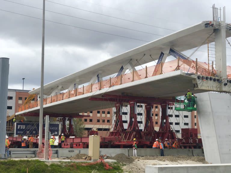
I have a bit of experience with SPMTs. They are really a wonderfully designed piece of equipment, there are several manufacturers now but they all operate the same way. All of the axle lines during a normal transport are on the same hydraulic circuit which allows each axle to stroke up and down independent of adjacent axle lines while maintaining a constant bearing, so crossing normal bumps and slight elevation changes are no problem. But the axles only have 1ft of up/down stroke so there are limits. Also they talk about them in terms of the number of axles but there really are no axles, they have independent, two tire hubs on either side of an axle line.

And just because I think they are so cool, here's some more. Any hub can be isolated and raised, for instance if a tire blows out. They can turn the hubs on either side of the axle line independent from each other so you can walk the trailer nearly 90 deg from its long axis, or almost pivot in place, wonderful things.
 
It's pretty clear from the pictures they had a hydraulic jack attached to the PT rod of a compression member. I understand why it was needed for transport, but once it was placed on the permanent supports it went from a tension member to a compression member.

They were jacking a PT rod in a compression member because in order to de-tension it you have to actually increase the tension first? Isn't that just putting more compression force into a compression member? If,during post tensioning, you damage the member or the member's connection to the rest of the truss you're screwed because there isn't any redundancy. How many times have you heard of something getting "blown out" during a post tensioning job?

It seems to me it would take a pretty darn sophisticated structural model to account for the affect of all these post tension forces in addition to the forces in the truss to due self weight.

Build a steel truss, if you need extra weight use an oversized concrete deck. Sometimes stuff seems really cool on paper, but it sucks in real life.
 
waross,
Re: The blue box.
Yes, you are correct. That has already been established in part I of this thread. Ingenuity even identified the manufacturer and model of the pump. He/she seems to have experience with it's use.
 
Tomfh said:
Agree. The truss members have to stabilize the top.

and because of the length, they would also have to stabilise the unbalanced load from the bottom flange, too or at least a large portion of it.

Dik
 
OSUCivlEng, the point you make about the PT in #11 probably being intended for the transport phase and then detensioning for the permanent phase makes sense and has been assumed by several of us here. The timing seems odd to me, if that was the intent of the design and the construction sequencing, wouldn't they have detensioned #11 before Thursday if the bridge was set on Saturday. There is a video of someone from the construction company mentioning detensioning 2 cables on top of the bridge after the bridge was set. I think the video is from the day the bridge was set (Saturday). It is not clear whether he was referring to the 2 PT rods in #11 or 2 of the longitudinal tendons in the canopy/top chord, but either way it seems like it would have been done before Thursday. Does that mean that the work being done Thursday was not the normal design/construction sequence, but was some sort of remediation for another problem, maybe the cracking that has been reported? Any thoughts?
 
Following on from my last post... if the intent was to detension #11 then wouldn't #2 probably get the same treatment? The construction company video mentioned detensioning 2 cables, but we think that #11 and #2 had 2 rods each, 4 total, so did he mean 2 members, or was he referring to 2 longitudinal tendons in the canopy/top chord and not the rods in the diagonals?

A lot of unknowns. It will be interesting to learn the details when they come out.
 
Here is a photo of a closer view of the north-end failure, from NTSB video:

CaptureMIAMI_NTSB_luy5b5.png


And another showing spalling to underside of member #11 - the same side that the PT bar that was being stressed/de-stressed was located:

CaptureMIAMI_NTSB_2_rv0qxo.png


NTSB B-roll video here: Link
 
Correct me if I'm wrong, but, with a prestressed compression member, the prestressing does not increase the compression loading... The member is loaded in compression until the prestressed value is reached before the stress increases in the section. Is that not correct?

Dik
 
Ingenuity said:
And another showing spalling to underside of member #11 - the same side that the PT bar that was being stressed/de-stressed was located:

So there were two bars in #11? Not a central bar?
 
dik said:
Correct me if I'm wrong, but, with a prestressed compression member, the prestressing does not increase the compression loading... The member is loaded in compression until the prestressed value is reached before the stress increases in the section. Is that not correct?

The loads are additive.
 

Nobody important (Computer)
Nobody Important said:
18 Mar 18 23:32
Just in case anyone is interested in a rough idea of the tension / compression loading of the trusses when:
A-In transit supported underneath in 2 places mid span
B-In Situ supported at either end of the span

These are not to scale or necessarily accurate, but give a general idea. Draw your own conclusions here.

That (rough) compression-tension FEA sketch is logical, and explains how the top members are in great compression across greater length/limited thickness elements = classic buckling failure at the odd-angled connections of each member that is in compression. But - Why would the "missing" center vertical temporary vertical pier NOT be installed?

Does the analysis/design team truly think that a cable-stayed bridge only needs the cable stays and central pier for "looks"?
 
Status
Not open for further replies.
Back
Top