Continue to Site

Eng-Tips is the largest engineering community on the Internet

Intelligent Work Forums for Engineering Professionals

  • Congratulations KootK on being selected by the Eng-Tips community for having the most helpful posts in the forums last week. Way to Go!

Miami Pedestrian Bridge, Part II 55

Status
Not open for further replies.
Ingenuity said:
Damn, it would have been a good research project for a select few FIU engineering students.

Could still be an educational endeavour... Careful you don't do this...

Dik
 
Re the compression effect on the force in the prestress, remember we are dealing with (in Metric) concrete strengths of 30 - 60MPa and prestress steel strengths of about 1800MPa. And Modulus Es / Ec of about 7-8.

So if there is 20MPa compression in the concrete (about the maximum allowed at .5Fc), then the reduced tension in the prestress will be about 20 * 8 = 160MPa, so about 10% of the ultimate prestress force, or up to about 15% of the force after stressing.
 
Has anyone worked out the load/stress in #11?
 
rapt said:
The relatively small amount of load that would have been applied by the stressing of one prestress bar in a diagonal should not be sufficient to cause the collapse if the overall design was ok. With normal factors of safety etc, the amount of force we are talking about compared to the overstrength required to be built into the design is insignificant.

I think the idea is that it may have pushed an already deficient (or otherwise compromised) structure over the edge. The proverbial straw that broke the camel's back.
 
Tomf said:
I think the idea is that it may have pushed an already deficient (or otherwise compromised) structure over the edge. The proverbial straw that broke the camel's back.

Exactly. What is pretty much clear is that the design and/or construction was defective. What is also almost certain is that the activities on the bridge by workers at the time were the trigger of the actual collapse.

My gut feeling is we are still largely talking about punching failure around the top connection. The cracking that was observed prior was likely this already happening. The works at the time was a supposed remedy. You have a thin top cord with high and concentrated punching loads from the web connections. It seems a fragile design to begin with. You want to get the reinforcing around those members done correctly.
 
TomH,

I think that is what I was saying! It was on the point of collapse at the time that the diagonal stressing (or it could have been destressing!) was being done.

The final straw may have been the works they were doing, but it should not have taken 1 straw to cause a collapse. In my experience a collapse normally requires bad design errors + bad construction errors + bad luck. Unfortunately they succeeded.
 
Tomfh said:
Has anyone worked out the load/stress in #11?

BA did a quick back-of-the-envelope calc, above [in 'pagan' units] as follows:

BAretired said:
Member 11 may have been a tension member during construction but it was a compression member after the temporary supports were removed. Assuming a total weight of 950 tons, the bridge reaction at each end would have been in the order of 950 kips under dead load only. Member 11 appears to be oriented at about 35o to the horizontal, so it would have been loaded to about 1650 kips, a compressive stress of 3,300 psi on a 24" x 21" section under dead load only. It did not need any prestress at that stage.
BA
About 23 MPa, in 'gods' units!
 
rapt, yes I think we agree. Clearly it was unhappy already.
 
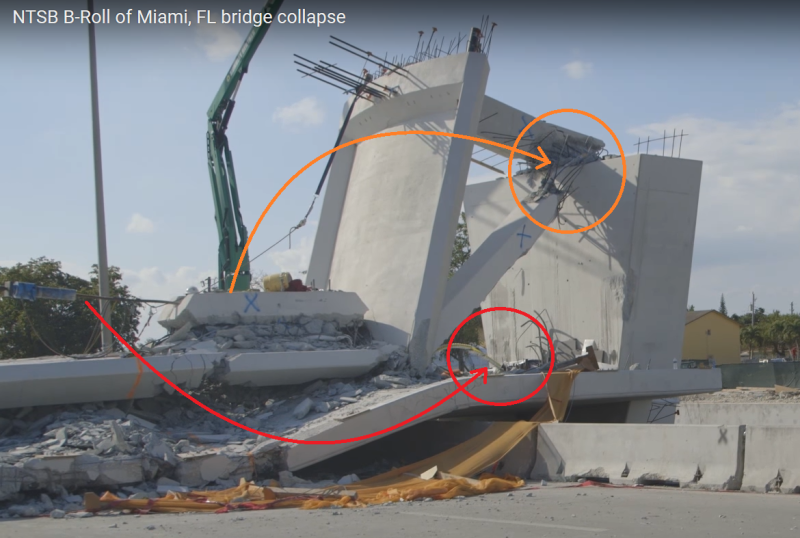
Looking a the collapse, I think it started as a failure in the bottom slab immediately on the outer side of the point where diagonal 10 connects (towards the support).

The movement of 11 happens slightly after the the slab to the outside of the connection at 10/11 disintegrates on the 10 side.
 
Probably the both anchors of member #11 tensioning rods.
One of them looks still attached on deck.
Member11anchors_drmwbz.png
 
The more I think about this the more concerns I have around the length of the main deck and lack of a proper 'I' beam.
This is a 50m concrete structure supported at either end with very little useful stiffening to stop longitudinal deflection.
You have a handful of asymmetrical concrete trusses and 12 longitudinal tendons stopping the deck from wanting to deflect down and buckle.
Add to that any structural weirdness that may have occurred during transport. Did the main deck longitudinal tendons start to fail, we assume they were PT'd and grouted.
Maybe the strange behavior around #11 pulled the trigger, but by way the largest forces in the bridge is the main deck in tension.
Did something fail around #11 that had a significant effect on the main deck tendons, which were already on their way out?
If you take away the compressive force of the longitudinal tendons at one end, you get a very similar failure pattern that is seen in the dashcams
 
If the longitudinal tendons fail, they would be unlikely to fail at the same time, so the deck would have twisted when that side failed first. If they had all failed at the same time, the deck would have been pushed apart by the compression load in the canopy.

The fallen deck is shattered, but continuous and it doesn't twist in a notable way on the way down, so it seems unlikely that the initial failure was due to the longitudinals. Since the deck is still tied together I expect the longitudinals are still continuous.

I don't know how much twist would happen if only one of the longitudinals near the center line failed, but it seems likely that there would have been a cascade of failure, again yielding either twist or separation.

Since there was no twist and the deck and canopy are still tied together without notable separations, the failure is somewhere else. The only other place is the truss-like members and their attachment to the deck and canopy.
 
3DDave,

If you watch the video, there is a pronounced twisting of the upper deck as the truss fell.

Were the longitudinal tendons grouted? I thought not, someone said they were, but I am not sure.
 
Does it bother anyone else that during transportation on the failed side one the transporter looks like it is in the middle of a span and not on a node?
 

I would imagine the 2 cables to be detensioned would be in the top chord or "canopy" of the bridge since it would be a compression member once the span was set in place. Let's also not forget that the span had been in place for 5 days before it collapsed. I don't think what they were doing on Thursday was part of the design/construction sequence, it was a remedy for the cracking that had occured.

My hunch is the adjustment to the PT rod in member #11 had to do with the cracking that was found, and was the subject of the voicemail by the FIGG engineer to the FDOT engineer. They had a 2 hour meeting about the cracking a few hours before the collapse. Engineers for FIGG "delivered a technical presentation" about the crack. The crack was on the north end and they were messing with the rod on the north end, I don't think that is a coincidence. Like others have said, the tensioning/detensioning action was probably the straw that broke the camel's back.

By now I'm sure there are people who know exactly what happened, but can't or won't talk because of legal fears and orders from their lawyers or employer.
 
The 'cable stays' have no bearing on the collapse, but, may have merit if the installation of the bridge required 'some' support at their locations. No one has provided a procedure for the installation of the bridge, and, this may come out in court if for no other reason than to cloud issues.

The cable stays, although decorative and not in place, would have an influence on the overall behaviour of the bridge. 8 - 1-1/2dia bolts (grade and anchorage unknown) would have a significant impact on load transfer. The stay, although on an angle, is in axial tension and has the axial stiffness of a steel member, whereas the bridge is concrete and in flexure.

Because they are above the shear center, they would also provide some stability.

Dik
 
I agree with OSUCivlEng's comments...

The stressing of #11 was due to cracking that was observed and was an attempt to fix an existing issue. And I do not believe they were destressing it, but were stressing the tendon...Though #11 may have caused the collapse...the collapse was due to a design failure of inadequate shear capacity.

Lets's assume Hokie's numbers are correct and that there is 1650K of compression in #11...Though we want to consider #11 with pinned ends..it is not..and is acting like a beam. The vertical shear at the bottom end of #11 would be about 950k...therefore Vu would have been about 1330k!...If f'c=6ksi...PhiVc would only be about 60k...there is not enough room in #11 (24"x21") to provide enough stirrups to handle the vertical shear in that member.

I believe that prior to failure #11 had some upward bending (concave up) and had cracking on the bottom side of #11. To address this, the engineer attempted to tighted the lower strand. The rupture first occurred at the bottom of #11..and with #11 removed..hinges were formed in the bottom of the slab near #10 and the top of the slab adjacent to #11.

When I step back and look at #11...It just doesn't not look big enough to handle the shear loads that would be imposed.


nothing so far has nailed down the triggering cause of the collapse....I still maintain that hokie66's comments on the conc truss and it's potential problems especially @ the connections where the possibility of development of incidental moments could occur may well hold the clue to the collapse..also no mention so far of mild stl reinforcing @ the joints...frankly, the magnitude of these loads would scare me as I have never done any PT design...
 
Structuralengr89,

I agree with your assessment. And you brought up another point which I had not thought of, namely that in addition to its poor performance in tension, the high E of concrete makes it a terrible material for use in a truss. Idealized trusses use pinned connections at the joints, steel trusses have enough flexibility (and redundancy in the material) that even though our nodes and connections are stiff, it still behaves mostly like an ideal truss. Concrete does not have that luxury, being such a rigid material it cannot accommodate the small rotations required at the points of intersection, and once it cracks it has lost all of its shear strength. If the design accounted for the shear strength of concrete + rebar (I'm making a leap here), when the PT rod let go and the member 11 lost the compression holding it together..........

Can someone who designs reinforced concrete please tell me how you typically design for shear in reinforced concrete?
Just Rebar or Concrete + Rebar?
 
Status
Not open for further replies.

Part and Inventory Search

Sponsor