Continue to Site

Eng-Tips is the largest engineering community on the Internet

Intelligent Work Forums for Engineering Professionals

  • Congratulations KootK on being selected by the Eng-Tips community for having the most helpful posts in the forums last week. Way to Go!

Miami Pedestrian Bridge, Part II 55

Status
Not open for further replies.
Ingenuity said:
About 23 MPa, in 'gods' units!

cubits?
 
Was it here that it was mentioned that the founder of the bridge company died a while back. I think this is described in Petrovski's Engineer's of Dreams, where a successful company fails to maintain continuity of expertise, allowing the reputation to exceed the capability. The founder worked his way from smaller projects and probably encountered smaller failures which were overcome and thereafter avoided. The newer management didn't get that experience.

It would have been so easy to take this bridge, lift it at the same locations and set it back down on the construction site with simulated pylons, perhaps only a few feet above the ground, and do actual load testing and so forth before placing it. They could have made multiple engineering class projects out of it; measuring deflection and comparing it to envelope calculations and sophisticated computer models over a couple of semesters before finally placing it. It's supposed to be in place 100 years; 8 months is very little to ask.
 
I'm ready to make a small bet. By the time his gets in court and resolved, all the time and energy will be spent on who gets sued and how much. All these engineering theories will never be mentioned in court OR WHO IS AT FAULT. SPEAK FROM EXPERIENCE.
 
OG: concur
 
@hokie66 - you're going to have to start Part III pretty soon.

BTW, does anyone know where KootK has been? I'd be interested in his perspective.
 
KootK said:
BTW, does anyone know where KootK has been? I'd be interested in his perspective.

Knowing him, he's likely read the whole thing.

Perhaps he's doing like I am and not guessing until we have more factual information? Not disparaging any for their current discussion; only that I personally prefer to wait until more information is available in things like this before I discuss it.

Professional Engineer (ME, NH, MA) Structural Engineer (IL)
American Concrete Industries
 
structuralengr89 said:
Please tell me this article is fake:

Snopes says it is. I found this by Googling "florida bridge women". I Googled the title of the Sandra Rose article, and I found no web or blog sites that I know to be reliable.

I have corrected this to link to Snopes, as I originally intended. There is lots of anti-snopes stuff in the comments to the Sandra Rose blog. I observe that the post I was replying to has been deleted.

--
JHG


LittleInch said:
Am I the only one who is concerned about the mismatch of diagonal supports? The members 2,4,6,8 and 10 all point more or less the same angle one way resisted only by nos 11 and 9 pointing the other.

Does this not induce a force which is essentially trying to push the top section to the right (North end) heaping even more misery on the no 11 support? (see Ingenuities diagram on 18 mar 20:55). Also this is where the initial collapse was focused, but may have been due to other issues.

I think this is correct. The reverse slope of diagonals 3 and (almost) 5 would have concentrated the compressive and bending stresses in the canopy towards the side of the bridge that failed.

It's possible/likely the asymmetric design of the truss, executed in service of making the bridge look like a cable-stayed structure, will prove to be an important factor in creating stresses the bridge design may not have fully anticipated.
 
LittleInch said:
Certainly fiddling about with the PT bars in that overworked no 11 strut was clearly not a good idea, but is this simply a flawed design from the get go?

Like many people I suspect that's what it boils down to. Tensioning and snapping a bar in a compression strut shouldn't bring the thing down.

I'd put my money on #11 struggling and failure being triggered by the PT in some way or another.

We won't know for sure until we find out where the crack was and what exactly the guys were doing up there. It's a public enough disaster that I suspect we'll find out. At least I hope so.
 
3DDave said:
8 months is very little to ask

I find people get angry enough if you cost them a day.
 
mibro said:
the asymmetric design of the truss, executed in service of making the bridge look like a cable-stayed structure

That's the strangest part of all this. The bridge was a intended to be fake. Decorative tower and cable stays?! What a bizarre concept.
 
Tomfh said:
That's the strangest part of all this. The bridge was a intended to be fake. Decorative tower and cable stays?! What a bizarre concept.

Yup, it gets stranger the more you think about it. What an odd series of design decisions when an actual cable-stayed structure would arguably have made a lot more sense. At the least it would have removed a hard-working concrete truss from the design.
 
Yep, and it would have been able to be built out on a cantilever basis. Maybe shut down a lane or two over time, depending on the sequencing. Or, alternatively, use a steel truss for their accelerated construction concept.

Speaking generally, the default mode of concrete joints is fixed while the default mode of steel joints is pinned. Each can be made to do the other, but only deliberately and with (sometimes) great effort. Meanwhile my statics textbook, with one of this firm's (or it's predecessor's) bridges on the cover, tells me that a truss has pinned joints, by definition. Someone forgot the basics.
 
I'm wondering why anyone would even post a link to white supremacist/sexist propaganda. That garbage was on twitter on day 1. If you use your engineering brain, you could figure out that it is inflammatory propaganda that shouldn't even be allowed to stay on this forum. The EOR is W. Denny Pate. Google him. He's a well-respected Caucasian male in his 60s with many bridges under his belt.

Even if it were designed by a woman, why would anyone in their right mind blame what happened on that. For shame on this well-respected forum.
 
Tomfh said:
That's the strangest part of all this. The bridge was a intended to be fake. Decorative tower and cable stays?! What a bizarre concept.

It is a fairly common concept across the world. It is a given for buildings and is common in bridges. I would almost suggest that a majority of pedestrian bridges have decorative features. Please lets not go back 50 years to purely function buildings devoid of character and life.

(Even in steelwork in industrial production we occasionally make some choices that are about looking nice rather than purely engineering. Only occasionally though mostly things are simply about function in my industry.)

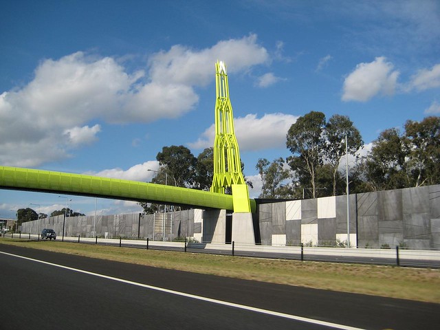
3036688576_f65ee12742_z.jpg


A simple concrete cantilever bridge which has fake towers simply to look more interesting.
 
Human909,

Yes, don’t get me wrong, I know decoration is common. Our Sydney Harbour bride for example has decorative pylons.

In this instance I’m taking about the actual structure itself. The structure itself - the member orientation etc - was designed as decorative adornment to the phoney towers and cables.

That’s completely different to when the architect sticks a couple of fins on the building.
 
True. True. :)

Archie264 said:
Yep, and it would have been able to be built out on a cantilever basis. Maybe shut down a lane or two over time, depending on the sequencing. Or, alternatively, use a steel truss for their accelerated construction concept.

Speaking generally, the default mode of concrete joints is fixed while the default mode of steel joints is pinned. Each can be made to do the other, but only deliberately and with (sometimes) great effort. Meanwhile my statics textbook, with one of this firm's (or it's predecessor's) bridges on the cover, tells me that a truss has pinned joints, by definition. Someone forgot the basics.
Forgetting the basics of pinned vs fixed seems surprisingly common in my observations. I'd hope it isn't common in bridge design but in more simple structure people seem to get lazy.

I was once involved in a construction where there were issues with columns bending on a simple single story structure. The structural engineer was blaming the fabrication/erection for it. I casually asked whether the column to beam joins were modeled as pinned connections to which the the engineer yes of course. I then pointed to the connection and asked does that look like a pinned connection to you? The columns were bending because the connection allowed significant moment transfer from the beam to the column.
 
I think the problems with this bridge begin with the boots on the ground.
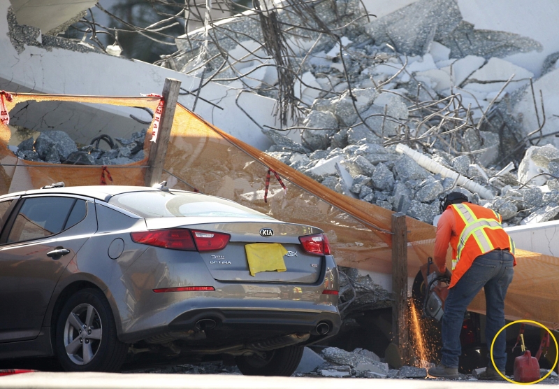
EP-3031977_pp1cc4.jpg
 
Just can't resist getting my 2 cents in on this one.

Question, was this concrete bridge cast monolithic, or are there some construction joints somewhere. I'm guessing each of the truss diagonals are individual members who's ends don't fit PERFECTLY together, maybe leaving small voids inviting crushing at the bearing points between members. Not sure about getting accurate calculation of shear across a construction joint either.

Also, I'm having a hard time believing an Engineer would CHOOSE to have the last diagonal in a concrete truss in compression, with a tendency to push it's way off the end if something failed.

Just watching.

LonnieP
 
LonnieP, the member orientation is to make them look like hangers aligned with the phoney cables above..
 
Status
Not open for further replies.

Part and Inventory Search

Sponsor