Eng-Tips is the largest engineering community on the Internet

Intelligent Work Forums for Engineering Professionals

  • Congratulations waross on being selected by the Tek-Tips community for having the most helpful posts in the forums last week. Way to Go!

Miami Pedestrian Bridge, Part II 55

Status
Not open for further replies.
House mover: Here's a re-post of the video.
hokie66 said:
hokie66 (Structural)
16 Mar 18 01:03
An article from heavy.com...there is a time lapse of the bridge move. Hopefully, some video at the time of the collapse will turn up.
I can't see the position of the transporter wheels.
They have the ability to castor individually or be steered individually.
I doubt that the wheels would be dragging sideays.

Bill
--------------------
"Why not the best?"
Jimmy Carter
 
BAretired said:
Member 11 may have been a tension member during construction but it was a compression member after the temporary supports were removed. Assuming a total weight of 950 tons, the bridge reaction at each end would have been in the order of 950 kips under dead load only. Member 11 appears to be oriented at about 35o to the horizontal, so it would have been loaded to about 1650 kips, a compressive stress of 3,300 psi on a 24" x 21" section under dead load only. It did not need any prestress at that stage.

At that cross section and length, how stable would that member be against buckling?
 
We should remember that the drawings we have seen are preliminary or proposal drawings. The construction drawings may well differ. The pipe stays are one thing that could have been changed to allow movement. The cast in bolts could have bolted down a bracket, which then had a slip connection to the pipe. But that is conjecture, and I agree if built the way the preliminary drawings show, the stays would have changed the way the final structure worked dramatically.

Lonnie P asked if the truss/frame was monolithically cast. I think it was, more or less. There must have been some construction joints, but I don't think it was a matter of precast elements being connected together.
 
Lnewqban said:
Additional questions about the tensioning process for anyone that may know:
1) Can the plastic flow of the steel, prior snapping, be seen in the gauge or be informed to the operator by some kind of alarm?
2) If so, does the hydraulic machine have any automatic device that prevents it from applying additional tension to the cable/tendon/tensioner beyond its yield point?
3) Can the machine fail in a way that excessive force is applied (failing switch, inaccurate gauge)?

The stressing equipment used on this project at the time of collapse was very simple in design and use. Basically a 10,000 psi MAX pressure hydraulic pump (electrically operated, with a wired remote), with a 4-way valve (controls fluid directional flow), a gauge, a set of hyd hoses that connect to a center-hole, double-acting ram/jack, that sat upon a big-a$$ stressing stool/chair whereby the 'stressor' can turn the nut.

This hyd design/setup is about 40 years old - tried-and-true. Simple.

Stressing equipment gets calibrated, typically every 6-12 months, and sometimes right before significant use. It is usually calibrated as a 'system' - the pump, jack, gauge - using a load-cell, and traceable back to NIST standards.

If you have a 200 ton jack setup on a 150 ton capacity PT bar, then it is possible to fail the bar during stressing. BUT this did not happen on this project. The PT bar did not undergo tensile failure.

The answer to all three of your questions is a general 'NO'.

There is equipment that is more sophisticated, and incorporates displacement gauges and in-line load cells, etc., but not particularly well suited to typical field operations.

A more specific answer to your question #3 is more to do with operator error (or stupidity?) than equipment malfunction. A hyd pump and a 4-way valve is very simple in operation. Provided the operator is trained and experienced in stressing, knows what the stressing force (gauge pressure) is, then seldom (very seldom) do bars get overstressed. There are also pressure relief valves on pumps and rams to avoid overload above 10,000 psi (700 bar).

Keep in mind that the 1-[sup]3[/sup]/[sub]4[/sub]" grade 150 ksi bar was stressed to 280 kips (max), about 70% of UTS. The bar has a ultimate tensile strength of 390 kips - so for an operator to go way beyond 280 kips - all the way close to 390 kips (40% more) - would take a huge screw-up.
 
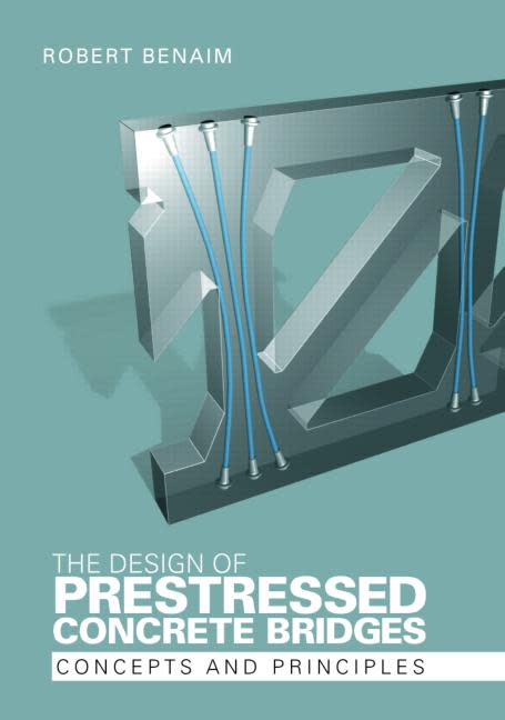
Cover of Benaim's text of PSC bridges...

capture_psc_book_qa3q2b.jpg
 
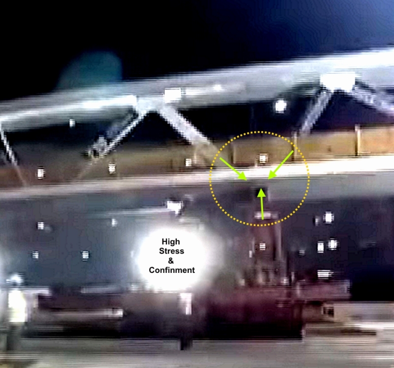
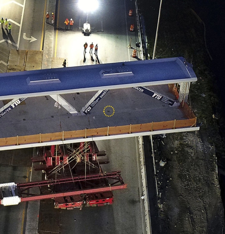
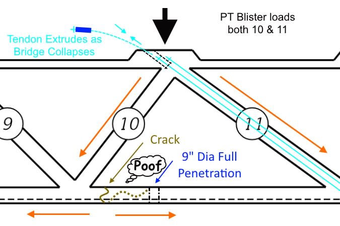
Why would a crack form in an area that is under considerable compression both from the PT tendons and the overhanging load?

The distance between the canopy and the deck remains constant at #10, while outboard of #10 they both hinge together.
 
steveh49 said:
That would depend on the contract. But you're in a better position if the money's in your bank account than theirs. D&C probably helps too since it doesn't matter whether it was a design or a construction error, it all 'your' problem from the client's perspective.

I've never had a project that 'stopped' so abruptly... had a couple where the contractor went bankrupt and one where the contractor was terminated with questionable cause.

I would think that the contractor should be given the opportunity to make good, or, be sued for non-performance, but, I'm not sure. It gets real cloudy if you decide you no longer want the 'bridge'. Unless the contractor is terminated, he has every contractual right to complete the bridge (not likely he would).

As far as withholding the funds, there is a 'legal' out. Since the last draw, the work has been rejected for reasons... a legal contractual out. I occasionally have had clients that don't like something and want to withhold funds, and, pointed out contractually unless the work is rejected as non-compliant there is no easy manner of legally withholding funds. Contractually, it's usually black or white, with no allowance for grey.

Dik
 
The Governor of Florida suspended all remaining Federal payments to MCM. Since it's Federal money it passes through FDOT first.

FDOT is trying to get out in front of this and distance themselves as much as possible. I haven't heard or read of anyone pointing any fingers at them.

Also interesting that FDOT says it didn't know of any "stress testing" (????) that was going on before the collapse.

"Over the weekend, FIU said the cracks were the subject of the two-hour Thursday meeting with FDOT, in which a FIGG engineer “concluded that there were no safety concerns and the crack did not compromise the structural integrity of the bridge,” according to a statement. FDOT then responded by saying its consultant who attended was acting in an administrative capacity only to ensure that the project was on time and still qualified for federal funds."

Really, the DOT sends a non engineer consultant to a meeting about a bridge being constructed over Florida SH-41? I know a little bit about a pedestrian bridge that was built over an interstate in the state where I live. The DOT here was all over every detail of the thing like stink on a pig's butt. Maybe hindsight is causing folks at FDOT to realize they should have exercised a bit more oversight over a bridge being built over one of their highways?
 
Hokie said:
They killed 6 people. They have more to worry about than getting paid.

Agreed... and, there could be criminal charges forthcoming, and how to prevent this from occurring again... something has to be learned from this terrible situation, but, someone is likely looking into how to 'wrap up' the project and what to do next. Was the bridge really necessary? will they construct another one? how are finances recovered? Lots of little unresolved questions.

Dik
 
OSUCivlEng said:
FDOT then responded by saying its consultant who attended was acting in an administrative capacity only to ensure that the project was on time and still qualified for federal funds."

They can say what they want. That won't stop them from being included... he may have been party to the cause/harbinger of the failure and he was likely an engineer... and FDOT has money... It would be interesting to see what was presented at the meeting and see the minutes of that meeting if they had time to prepare them.
 
So just out of curiosity, who here has ever "stress tested" an newly built structure? (I know its media BS, please don't think I'm that naive). I have weighed things, load tested things that need certification, and proof loaded structures that have a life saving function, but have never seen a "stress test" outside of a university laboratory.
 
Another reason I haven't joined the discussion here. Premature discussion here without all the facts may run against section 2.5 of the engineering code of ethics. Whether eng-tips posts are "public" is debatable (I'd argue that it's not) but regardless they are available to the public and could be quoted by media. Just keep this in mind when you post here.

Professional Engineer (ME, NH, MA) Structural Engineer (IL)
American Concrete Industries
 
EPCI: We stress test overhead cranes and custom lifting devices, it's mandated by OSHA and CMAA. Of course, it's not done over people or (hopefully) in an unsafe manner but for cranes it's often done in the final installed location.

Professional Engineer (ME, NH, MA) Structural Engineer (IL)
American Concrete Industries
 
EPCI: Oh, I misread your question. You're referring to specifically putting strain gauges on a structure (or similar)? Only one I know of off the top of my head outside of university was the Penobscot Narrows cable stayed bridge near me (interestingly enough also designed by FIGG) was installed with strain gauges on a few specialized carbon fiber cables to measure they're performance over time. I don't know if this is common or not to put strain gauges on modern cable stayed bridges but I remember them touting the fact that the DOT can monitor the stresses and loading on the bridge remotely via these gauges.

Professional Engineer (ME, NH, MA) Structural Engineer (IL)
American Concrete Industries
 
Now that is interesting. I forgot about this. I was at Texas Tech for high wind design class many years ago and they showed us how they build full scale buildings, instrumented them up with strain gauges and pitot tubes and used borrowed military aircraft to wind load them until failure. We only go the see them shoot 2x4's through a wall, but they showed us the videos and results of their testing. I would have liked to have been involved in that.
 
dik said:
We missed you... You just have to be careful about how you reply...

Thanks. I'm hoping we can get some idea of the joint detail that went into the frame before I start contributing to this discussion. I suspect we'll find that this bridge works more like a Vierendeel bridge than a truss bridge but between the angled web members, the post-tensioning, and all the unknowns I don't want to dive into it much further until we have more factual details. Just way too many things that could change whether this was a design error or not.

Professional Engineer (ME, NH, MA) Structural Engineer (IL)
American Concrete Industries
 
Status
Not open for further replies.
Back
Top