Continue to Site

Eng-Tips is the largest engineering community on the Internet

Intelligent Work Forums for Engineering Professionals

  • Congratulations GregLocock on being selected by the Eng-Tips community for having the most helpful posts in the forums last week. Way to Go!

Miami Pedestrian Bridge, Part VI 31

Status
Not open for further replies.
Apologies on last post (1 May 18 01:00), photo resolution us upscaled, so it is no better. Pedro Portal is still good source of photos.
 
Yes, 2 and 11 blisters were open during transport. My question is whether they were filled in (and then opened again) between March 10 when the span was set in place and March 15 when the bridge collapsed.
 
My posts were meant to summarize everything here after getting new specs showing PT anchors and reinforcement in deck, and to add the 3D stress analysis. I got sidetracked with the blisters... I'd been through all posts a couple times, but went back to beginning as 3DDave suggested and found where Rubio, on the first day (and had inside info), said the rods were being tightened when the span collapsed.. there still seemed some question about this.
------------------------------------------------------------------------------------------------
The Mad Spaniard said:
the node concrete side faces are compromised by the vertical PT holes and the drainage pipe hole.

This has been discussed a bit, along with a suspected cold joint at the deck/member junction - which was confirmed in the latest spec.
pour_spec_p73ynd.png


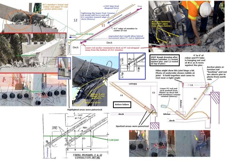
A "summary collage" (high res attached) shows the bottom of post-collapse #12 on top of pier.
It's fairly flat with rebar hanging out, and appears to have sheared at the cold joint.
The small insert shows intact highlighted area that was pulverized (Meerkat, IV 23 Mar 18 13:43).
02-FIU_failure_diagram-j_qonfvr.jpg

Bottom right shows large PVC pipes on sides of #12 intact (gwideman, IV 23 Mar 18 10:54).
Top right shows post-collapse with pipes still in deck. I'd assume #11 and #12 moved straight back - noted in video loop and frame grab sequence mentioned above (30 Apr 18 23:18).
A larger PVC pipe was below the cold joint, and #11 diagonal PT rod ducts crossed through it as larger ovals.
Spec shows no PT rods in vertical #12.
The upper PT rod anchor plate was within the "overhang", and has little concrete behind or to sides of it. Plate spec for 1.75" PT rod is 8"x12", but it doesn't look that big (exposed on top of pier).
This area was weak.

Lastly, the top center photo is from gwideman, IV 23 Mar 18 17:09. I suspect the #11,12,deck joint was stressed during the move and the cold joint/edge of the deck was affected. The upper rod had been tightened, and the lower rod was being tightened which would add to the dead load force pushing #11/12 north (total ~1927 kips/Peter's calcs; ~1400 kips horizontal with 30 degree member).
As Toomas noted, the edge and bottom of #12 were highly stressed, with only part of 12 attached to the deck. It's possible the workers were told to "give it a little more" on #11's PT rods because of the cracks - the rods were spec'ed at 280 kips, with typical (Williams) Min Ultimate Strength at 390. There appears to be some spalling (epoxybot, V, 29 Mar18 05:33) where the "overhang" sheared, as the deck fell.

 
Right before posting was temporarily halted on this thread, there were several individuals, Gwideman and MikeW7, who appeared to be working towards tracking down the original (or close to original) dashcam video and creating a zoomed-in video loop of the north end of the bridge. It became apparent that previous video loops posted herein of the collapsing bridge were created from video of unknown history (i.e. poor quality), or had been digitally manipulated to create super-slow motion with zero vehicle movement.

Am I the only one who thinks that analysis of the original dashcam video would prove exceedingly interesting and useful to the general public? Particularly, a zoomed-in loop of members 10-12, beginning at least one second prior to any noticeable disturbance, along with the still images from this video loop. Maybe nothing new will be learned from investigating the video further, but you don't know until you try.

If anyone has the ability to create such a video and post here I think that in addition to myself the general public would find it extremely valuable. This is not my area of expertise. MikeW7 provided this link on 29 Mar 18 03:56 to a relatively high-quality video, but I don't know if this is the original. Link
 
TheGreenLama: I did ok with gwideman's loop and your frame grabs, but this one appears to show the northwest corner better (thought to be a "puff", but clearly isn't on this), and the tree's out of the background so #11/12 kick out is easier to see, but the bucket lift is still in the way. It's better with the span further from the edge. I put it on a 32" monitor and it's still very clear, so if someone could blow it up bigger maybe could see something better. It'd be the best quality video.

I read somewhere here that you can Pause, then single step Youtube fwd with "." and back with "," - it works and can see #11/12 end in 5 frames (can also move 5 sec fwd and back with horiz arrows).
=====================
SFCharlie: The video looks like same angle/light, but maybe not as high as the photo. Thanks - I'll look at it more later and try some screengrabs (just learned how to do this).
=====================
John R. Baker: I thought you were joking around... I still use an old 2MB slide phone so don't ask much from photos, but detail IS important here.
=====================
jasm: Not sure why you wanted to know if blisters had been cleared after placement. I saw the jackhammer there and thought maybe hammering triggered this (transmitting impact to lower end), but after seeing the hyd jack on end of rod, figured they weren't jackhammering around it.

 
chris snyder - Peter Dow's analysis seemed to assume that the work done on Mar 15th was the planned destressing. The reason I'm asking about the blisters is that if the blisters were first filled in, then opened again on the 15th, then the destressing had almost certainly already occurred. In that scenario the Mar 15 work would instead be a late change of plan, likely in response to perceived problems with the bridge. This seemed to me an answerable question given all the footage that was shot between the 10th-15th.
 
To see minimaly degreated video zoomed in, download MP4 from above link, install VLC Media Player on your PC. Then play in interactive zoom mode and use [ ] keys to adjust playback speed. Sharpen image and adjust zoom to your liking. I cannot prove it at this point, but I was able to clearly differentiate falling concrete rubble from tree in background by using sharpen function. Please try yourself.
 
jasm said:
This seemed to me an answerable question given all the footage that was shot between the 10th-15th.
That's a valid question. I didn't see much video from the 10th-15th - only a few ones celebrating and PR'ing after the span was set.

The sequence of post-tensioning was:
1) Rods were tightened to prevent ends of span from sagging during transport
2) Span was set in place, and then rods loosened (on their own) as the #2 and #11 changed from tensile to compressive, and had to be tightened. Tony Pipitone said in video "the original design stress adjustments to those diagonal trusses were completed before the road was reopened last Monday morning" (spec sheet shows 280 kips for all these rods).
3) After the meeting on morning of the 15th, the engineer had them "add tension to the rods", which now (come to think of it) sounds like it would have to be more than 280 kips on spec sheet.

If someone has notes or a link where it says the rods were being destressed/loosened, I'd like to know... Peter Dow must have picked it up somewhere (though it almost seems the term "destressing" is being used for "post-tensioning").

They COULD have sealed the blisters after adjusting rods after span was set (before the road was re-opened), and opened them before adding tension on the 15th, but I don't know and it wouldn't affect the sequence or direction of post-tensioning.
 
jrs87: I had VLC Media player, but maybe my computer's too old. It doesn't play right consistently, but after doing what you said (zoom and slow), I think I can see a 'pointy' end on #12 lay on top of the pier. I tried 'screen shooting' it but it was blurry if I increased size. Will see what others say.
 
chris snyder said:
"computer too old"

Chris, transcode the mp4 to avi. MP4 compression codec gets in the way. AVI is much better for stopping and moving about timeline, MP4 depends heavely on data stream. How to transcode:
Keep in mind member 12, the tree, and the lift boom all line up at time of collapse. So it's difficult to rule out artifacts here. Sharpening helps.

I was able to "cast" video to 55" 4k television. It is clear the span dropped and held for a moment (cannot rule out video artifact), then events bounce between 12/11, 11/10, and 10/9. The next major event is 9 punching through folding deck. then 12/11 explodes, next 11/10 angle opens up and 11 can be seen going under top of 10. Finally 11 is shoved hard and the canopy and deck pancake. What I saw made me suspect something in the deck gave way first, dropped the span, and then geometry change was too much for the truss to bear.
 
Thanks jrs87 (Mechanical)
Can you point me to more info on how to zoom (how do I get the little window that lets me pan the zoom area) and sharpening ( What is the "right" setting for the slider?"
Thank you,
Charlie
 
SF Charlie,

VLC Media Player Zoom: Ctrl+E > Video Effects Tab > Geometry Tab > Check Box Interactive Zoom > Save > Close

A zoom box will appear on playback and a zoom level slider will be near it. Speed of playback: every press of [ is slower, ] faster.
 
jrs87,

How do I extract? Are these JPG files? What App to use?
 
As far as whether or not the "puff" is a bridge corner, it is not. The reason I say this is that early in the video, you can see the bridge corner to the left of the vertical man lift mast. This is at a point in truck travel, that you can compare the left, & right bridge corners. As the truck moves forward, the corner disappears. It would be impossible for bridge corner to pop back out on the left of mast as the truck moves forward.
 
Cutterhead said:
"How do I extract?"

This is 7 Zip file of 111 .jpg files. Needed extra compression due to forum limit. Extract with the Windows program 7Zip. This is a very common mainstream program.
 
Status
Not open for further replies.

Part and Inventory Search

Sponsor