OK ... I was given the job of duplicating a "simple" box that monitors air flow in a duct.
Seemed simple ... I dabble in electronics (I design and build industrial control panels .. starts ...plc's ... HMI ....)
I knew the guy who designed and built the originals about 25 or 30 years ago ... long since retired and passed
SO ... I found an old drawing we had ... hmmmm ... does not match the circuit.
I traced the board ....
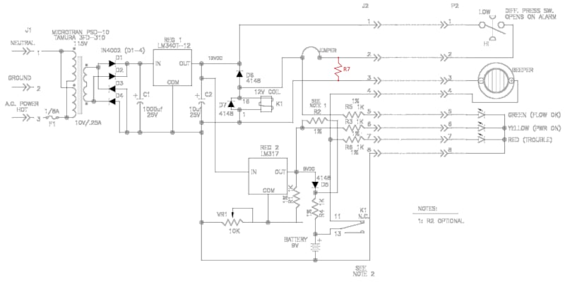
1) R7 (drawn in red) is a 1.2K resistor not on the drawing but on the board. It is not something added in later as it even has artwork on the board for it. I don't understand what it is for ... just adds load (maybe needed as the relay only draws 30mA)?
2) Don't understand D6 ... D7 is for voltage foldback(flyback diode) but why D6 ?
3) R2 says optional but is installed on all boards. I don't see what it does as it bypasses D5 ... which is a problem as it backfeeds the yellow led (glows on even when power fails).
4) "see note 2" .... no note 2
And now my big question ....
Reading the data sheets, I see the LM317 (REG 2) is fed from the 12 volt regulator REG 1. The LM317 requires 3 volt differential to operate properly.
This means I can get 9 volts at best out of REG 2. After going through the diode D5 ... maybe 8.5 volts.
The battery is a 9 volt NiMH ... 8.4 rated voltage... 7 drop off ...10.5 max charging
I checked the units .... 7.24 volts at the regulator! After sitting a while (put in a new battery) the same voltage at the battery!
OK, so I know these are working ... and I know they have been used for years ... but how is the battery changing at only 7.24 volts?
The beeper is a sonalarm ....6-28 volts at 6-26 mA ... maybe if you charge the battery at only 7.24 volts it will stall have say 10% of it's capacity. So a 280 mA battery will still have maybe 28mA ... enough to keep the buzzer going for an hour (which is probably fine) ?
Just never heard of "under charging" .... the boss just wants me to duplicate this ... am I missing something?
Seemed simple ... I dabble in electronics (I design and build industrial control panels .. starts ...plc's ... HMI ....)
I knew the guy who designed and built the originals about 25 or 30 years ago ... long since retired and passed
SO ... I found an old drawing we had ... hmmmm ... does not match the circuit.
I traced the board ....
1) R7 (drawn in red) is a 1.2K resistor not on the drawing but on the board. It is not something added in later as it even has artwork on the board for it. I don't understand what it is for ... just adds load (maybe needed as the relay only draws 30mA)?
2) Don't understand D6 ... D7 is for voltage foldback(flyback diode) but why D6 ?
3) R2 says optional but is installed on all boards. I don't see what it does as it bypasses D5 ... which is a problem as it backfeeds the yellow led (glows on even when power fails).
4) "see note 2" .... no note 2
And now my big question ....
Reading the data sheets, I see the LM317 (REG 2) is fed from the 12 volt regulator REG 1. The LM317 requires 3 volt differential to operate properly.
This means I can get 9 volts at best out of REG 2. After going through the diode D5 ... maybe 8.5 volts.
The battery is a 9 volt NiMH ... 8.4 rated voltage... 7 drop off ...10.5 max charging
I checked the units .... 7.24 volts at the regulator! After sitting a while (put in a new battery) the same voltage at the battery!
OK, so I know these are working ... and I know they have been used for years ... but how is the battery changing at only 7.24 volts?
The beeper is a sonalarm ....6-28 volts at 6-26 mA ... maybe if you charge the battery at only 7.24 volts it will stall have say 10% of it's capacity. So a 280 mA battery will still have maybe 28mA ... enough to keep the buzzer going for an hour (which is probably fine) ?
Just never heard of "under charging" .... the boss just wants me to duplicate this ... am I missing something?
")