Continue to Site

Eng-Tips is the largest engineering community on the Internet

Intelligent Work Forums for Engineering Professionals

  • Congratulations KootK on being selected by the Eng-Tips community for having the most helpful posts in the forums last week. Way to Go!

replicating an old circuit- unexpected voltage drop

Status
Not open for further replies.

jabba99

Electrical
Jul 5, 2024
11
I'm fairly new to circuit design and i stumbled upon this old fashioned circuit everything is fine on the breadboard but i was surprised when i put it on the pcb that whenever i put a resistor parallel to the 10V line ( i need it for the rest of the circuit) the voltage drops to about 4V. I triple checked everything and it's fine. any tips on what could be the issue?

simplified_schem_krfzdn.png
 
Replies continue below

Recommended for you

Right back to my first post. It's a voltage divider.

I now find it very hard to believe that the circuit with the load connected works on a breadboard.
 
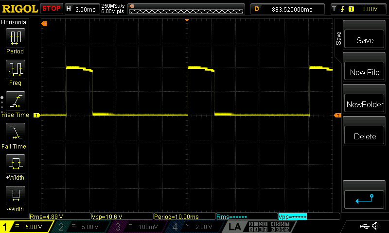
it does work as i said when i put the entire circuit on the breadboard i get the results put the PCB has an issue

NewFile1_hpptdo.png


I'm starting to think that the traces aren't wide enough and could be affecting the circuit. I'm using 0,3mm thoughout the entire board.
 
The load can't be 560 ohms then.

It doesn't compute. 560ohm load with that 56k series resistor means that less than 0.9% of the input voltage gets applied to the load. Say you were able to use the full peak of the applied 230VAC. That is 325V peak and 0.9% is 2.9V.

You've got a scope. Compare the breadboard and PC board version and determine where the issue is.
 
Based on your scope measurement, the resistance has to ~1200 ohms. However, that's still below the zener voltage because even 1200 ohm is too large a load for the 56k resistor

TTFN (ta ta for now)
I can do absolutely anything. I'm an expert! faq731-376 forum1529 Entire Forum list
 
Status
Not open for further replies.

Part and Inventory Search

Sponsor